SECTION TWO - Installation
961 INSTALLATION MANUAL Revision A
Page 11
Flush mounting
For flush-mounting the unit, allow at least 2½-inch clearance at the rear
for cables and connectors.
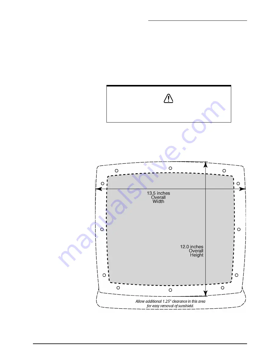
For the recommended flush mounting drilling dimensions, see Figure 3
below. For the full-size version of the flush-mount installation measure-
ments and instructions, refer to the full-size flush-mount template (P/N
GT1600) included in the 961 shipping carton.
Make sure you provide for adequate ventilation, especially if the unit is
installed in a closed area that’s usually poorly ventilated. Poor ventilation
will cause the head to overheat, which in turn may cause the display
screen to darken.
Figure 3: 961 control head flush-mount drilling dimensions
CAUTION!
When flush-mounting, be sure to mount the unit on a flat sur-
face. Mounting on a curved surface can distort or break the
plastic and cause a breech in the waterproof seal.
Summary of Contents for 961X
Page 2: ......
Page 4: ......
Page 6: ...Page ii 961 INSTALLATION MANUAL Revision A ...
Page 10: ...Page vi 961 INSTALLATION MANUAL Revision A ...
Page 54: ...SECTION TWO Installation Page 44 961 INSTALLATION MANUAL Revision A ...


