background image

36 


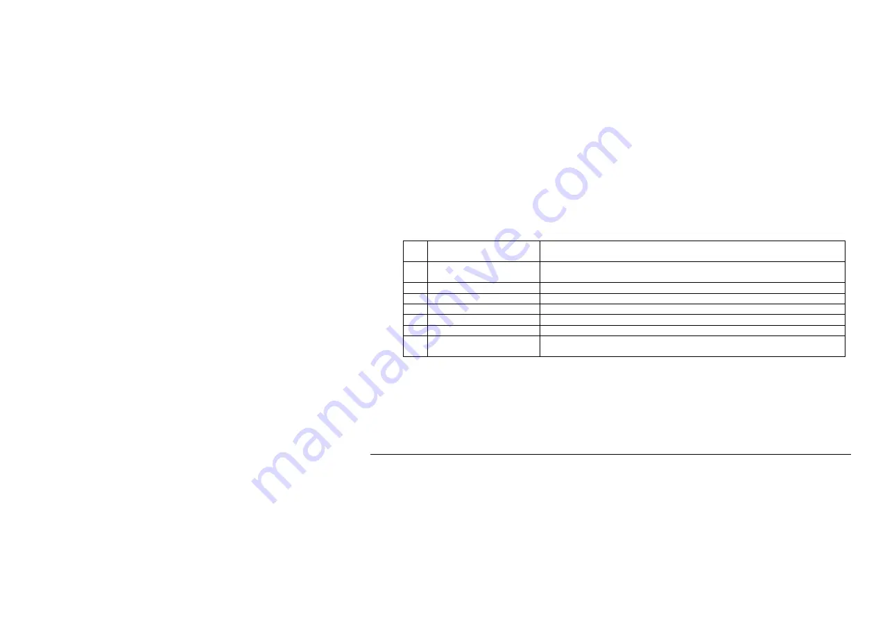
6.2  System selection and frequency setup 

Pressing the 

System/Frq

 button below the screen accesses the system selection and frequency setup menu. 

 The menu items are: 
 

[ Choose system ] 

Choose if you want to measure LLZ, GP, MKR or VOR. Subsequently 
you will be asked for the frequency for the selected system. 

[ Scan freq. ] 

Let the instrument scan through the frequency range to find a used 
frequency 

* Available for user-defined setup shortcuts 

* Available for user-defined setup shortcuts 

* Available for user-defined setup shortcuts 

* Available for user-defined setup shortcuts 

* Available for user-defined setup shortcuts 

[ More … ] 

Show more user-defined setup shortcuts if more than can be fitted 
into this page 


Summary of Contents for NORMARC 7710 NAV

Page 1: ...NORMARC 7710 NAV ANALYZER User Manual 23327 Rev 1 6 ...

Page 2: ...e system stated in the Title Page It shall not be used for purposes of product manufacture Copyright 2009 Northrop Grumman Park Air Systems AS The information contained herein is the property of Northrop Grumman Park Air Systems AS and may not be copied used or disclosed in whole or in part except with the prior written permission of Northrop Grumman Park Air Systems AS or if it has been furnished...

Page 3: ...TBR BGR Rev 1 3 Rev 1 5 4520 4439 21 Feb 08 JDA Rev 1 4 Rev 1 6 4498 10 Jul 09 BGR Rev 1 5 Changes Incorporated Issue Paragraph Paragraph Heading Description of Change Rev 1 1 General Corrections Drawings and text corrected Rev 1 2 4 2 5 6 and 7 1 New text and diagrams added and general corrections Rev 1 3 7 2 Added Calibration text E CR 2127 Rev 1 4 7 1 2 Added Charging maximum temperature text P...

Page 4: ...v Changes Incorporated Continue Issue Paragraph Paragraph Heading Description of Change Rev 1 5 General Added new functionality updated pictures 5 3 3 New DDM LP description Rev 1 6 All New company name ...

Page 5: ... 9 3 2 Charging the batteries 9 3 3 Connecting to RF signal 10 3 3 1 Using the supplied antenna 10 3 3 2 Using another RF source 10 3 4 Turning the instrument on 10 3 5 Turning the instrument off 10 3 6 Screen saver 11 3 7 Backlight 12 3 8 Connecting a computer to the NAV Analyzer 12 4 HOW TO OPERATE THE INSTRUMENT 13 4 1 Using the pushbuttons and the wheel 15 ...

Page 6: ... Standard measurements 21 5 2 2 Audible ident 21 5 2 3 Audio Baseband signal 21 5 2 4 IF signal 22 5 3 Various settings 22 5 3 1 How to select μA for DDM 22 5 3 2 How to define 90Hz 150Hz dominance for DDM 22 5 3 3 How to set up lowpass filter for DDM 23 5 3 4 How to set up averaging when doing measurements 23 5 3 5 How to set the correct attenuation 24 5 4 How to do procedure measurements 24 5 4 ...

Page 7: ... a computer Win XP 30 5 6 3 Connecting via network with DHCP server 33 5 7 File management 34 5 8 How to upgrade the NAV Analyzer software 34 6 MENU REFERENCE 35 6 1 Power menu 35 6 2 System selection and frequency setup 36 6 3 Measurements 37 6 3 1 When measuring LLZ 37 6 3 2 When measuring GP 40 6 3 3 When measuring MKR 42 6 3 4 When measuring VOR 43 6 4 Parameter setup 45 6 5 System 46 7 MAINTE...

Page 8: ... Maintenance 47 7 1 1 Batteries 47 7 1 2 Charging maximum temperature 47 7 1 3 Charging problems 47 7 1 4 Use of alkaline batteries 50 7 1 5 Corrective maintenance 50 7 2 Calibration 50 7 3 Software Updates 51 ...

Page 9: ... 0004 0 0004 0 0004 0 0004 RF level dynamic range 0 dBm to 80 dBm 10 dBm to 70 dBm 0 dBm to 80 dBm 0 dBm to 70 dBm DDM range 0 40 0 80 DDM Bearing error Centring 0 07 DDM Deviation 0 07 DDM 1 25 of DDM reading Centring 0 15 DDM Deviation 0 15 DDM 1 25 of DDM reading 0 3 SDM Mod depth range 0 95 0 95 10 50 80 100 SDM Mod depth error Subcarrier 0 5 SDM 1 SDM 0 5 Mod depth 1 0 Mod depth 0 5 Mod depth...

Page 10: ... Ident depth of modulation error 1 mod depth 1 mod depth Ident decoding Morse code decoded to letters Morse code decoded to letters Low Frequency error navigation tones 0 1 Hz 0 1 Hz 0 06 Hz 30 Hz 20 Hz 9960 Hz 1 Hz Low Frequency error Ident tones 5 Hz 5 Hz LF phase 90 Hz vs 150 Hz 0 1 0 1 Harmonic distortion 90 Hz and 150 Hz 2 3 and total distortion 2 3 and total distortion ...

Page 11: ...gnal with RF level 50 dBm to 20 dBm and temp range 10 to 30 C 2 dB 2 db 2 dB Resolution modulation 0 01 0 1 for Ident 0 01 0 1 0 1 Resolution LF phase 0 1 0 1 Resolution LF frequency 0 1 Hz 0 1 Hz 0 1 Hz 0 1 Hz Resolution RF frequency 0 1 kHz 0 1 kHz 0 1 kHz 0 1 kHz Resolution 30 Hz and subcarrier frequency 0 01 Hz 1 Hz ...

Page 12: ... 1 second step Sensitivity 20 dB SINAD in 3 kHz BW 80 dBm 70 dBm 80 dBm 80 dBm Selectivity 3 dB 12 kHz 60 dB 50 kHz 3 dB 25 kHz 70 dB 150 kHz 3 dB 24 kHz 60 dB 75 kHz 3 dB 12 kHz 60 dB 50 kHz Receiver image rejection 80 dB 100 dB 80 dB 80 dB Audio output noise level 180 mV rms 180 mV rms 180 mV rms Low pass filter Acc to ICAO Doc 8071 vol 1 para 4 2 9 Measurement rate 10 samples per second ...

Page 13: ... T with DHCP server RS 232 serial data 9 pins Sub D socket Event button input LF or IF output selectable Ident Voice audio jack GPS interface Used for LLZ center line run and crossover run Protocol according to NMEA standard RS232 connection CTS used for GPS Rx and RTS used for GPS Tx Tachometer interface Used for LLZ center line run RS232 connection CTS used for tachometer pulses RS232 levels and...

Page 14: ... hours use External charger 110 240V 47 63 Hz AC Power input 10 8VDC to 30VDC Battery charging time 4 hours Power indicators Low battery voltage Battery or charging Sleep Mode by Power button Night use Backlight on LCD Dimensions WxHxD 240 x 160 x 140 mm Weight 4 5 kg Antenna type Dipole telescopic Antenna return loss vs 50 ohm 10 dB 6 dB Antenna mast height 2 9 m 1 6 m retracted ...

Page 15: ...on Antenna alignment indicator Level Antenna cable Coaxial 4 m Temperature range operating and storage 10 C to 50 C 30 C to 80 C Protecting case Nylon bag with carrying strap Weatherproofness IP54 Data logging Software optional to be installed on a PC ...

Page 16: ...th of modulation 9960Hz Ident modulation RF level Frequency modulation index Carrier frequency subcarrier frequency Ident decoding The NAV Analyzer is a portable battery operated weatherproof unit to be used outdoors in a vehicle or inside the equipment shelter It is supplied with a dipole antenna with a unipod support and coaxial cable The analyzer has a rough outdoor design and is protected agai...

Page 17: ...o charge the internal battery Connect the battery charger to an electrical outlet and plug the other end into the rear of the NAV Analyzer Observe that the Power led after flashing quickly for a few minutes trickle charge changes to continues ON status charging battery If the led starts to blink the Morse code letter S the voltage of the battery cells is too low to start full charging In this case...

Page 18: ...coax cable if suitable NOTE Be sure not to overload the input The specification for the input is max 0 1W 20dBm 3 4 Turning the instrument on a Make sure that the battery is charged or that the charger is connected b Turn on the power switch at the rear of the NAV Analyzer c Press and hold 1 sec the Power button on the front panel 3 5 Turning the instrument off The instrument can be turned off int...

Page 19: ...rred mode during a measuring sequence when the instruments have to be turned off for moving to a new measuring Location To turn the instrument back on again press and hold 2 sec the Power button until the screen turns on 3 6 Screen saver To save power and thereby increasing the time the instrument can be used on battery a screen saver is built in To activate it a Press the Setup button and then se...

Page 20: ...yzer A computer PC may be connected to the NAV Analyzer for textual and graphical display of measurements storage of log files and maintenance of the instrument The connection can be made using the standard network connector Located at the rear of the instrument To connect directly to a PC use the included standard crossed network cable If using a network switch or router between the computer and ...

Page 21: ...4 How to operate the instrument Figure 1 The front of the NAV Analyzer 13 ...

Page 22: ...Figure 2 The rear of the NAV Analyzer 14 ...

Page 23: ... The main functionality includes Power on off setup and measurements Once the main operating mode is selected further functionality can be controlled through the buttons to the right of the screen The function of each button is different for each operating mode The descriptions of these buttons are shown on the screen beside the buttons themselves See an example in Figure 3 The wheel and left righ...

Page 24: ...Figure 3 Example screenshot with sub menu 16 ...

Page 25: ...off when it was put on charge it can not be turned on while charge is pending c ON instrument on full charge d Blinking slowly top off slow charging trickle charge 10h e Blinking Morse I temperature of the battery cells are outside their limits 0 50 Reduce or increase the temperature of the instrument f Blinking Morse S the voltage of the battery cells is too low to start full charging see 7 1 2 R...

Page 26: ...of the 12V level by monitoring the individual battery cells It is the cell with the lowest voltage that is shown The range is scaled as 0 100 corresponding to battery cell voltage from 1 0 1 3V a A green bar the battery voltage is better than 20 b Red square around text and a red bar the battery voltage is less than 20 c A blue full bar The battery is being charged ...

Page 27: ...u button Choose system 3 Select LLZ GP MKR or VOR 4 Select frequency 5 Optionally Add Replace Delete shortcuts 5 1 2 Automatic selection 1 Select the menu button System Frq 2 Select Scan freq to scan for any input 3 All frequencies with a detectable RF signal will then be shown 4 Select the frequency corresponding to the one you want to use ...

Page 28: ...ect the corresponding button 5 1 4 Adding shortcuts in the instrument For adding shortcuts through the instrument do this 1 Select the menu button System Frq 2 Select the submenu button Choose system 3 Select LLZ GP MKR or VOR 4 Select frequency 5 Optionally Add Replace Delete shortcuts Or through the web interface do this 6 Log on to the instrument see 5 6 7 Select the Administration link then th...

Page 29: ... menu button Setup select the sub menu button Audio and adjust the output level with the wheel 5 2 3 Audio Baseband signal The baseband signal contains the low frequency parts of the antenna input signal without the carrier frequency The signal is available at pin 4 on the RS 232 connector 9 pin D Sub at the rear of the instrument This pin is also used for the IF signal The procedure below shows h...

Page 30: ...the instrument see 5 1 2 Select the menu button Setup 3 Select the sub menu button Aux 4 Select the sub menu button IF 5 If necessary adjust the IF output level by using the wheel or arrow buttons 5 3 Various settings 5 3 1 How to select μA for DDM 1 Select the menu button Params 2 Select the button μA for viewing DDM as μA or the button DDM for viewing DDM in percent 5 3 2 How to define 90Hz 150H...

Page 31: ...des the averaging function described below When set to 0 0s off DDM is calculated using the average algorhitm if the average time is 0s 5 3 4 How to set up averaging when doing measurements 4 Select the menu button Params 5 Select the submenu button Avging 6 Use the wheel or up down buttons to set the number of seconds for averaging Example When selecting 2 in the Average field the calculations sh...

Page 32: ... i e CL Run is used when measuring continuous data The measure type procedures are used when you want to store data only at specified marks The procedures should be defined prior to running it default procedures exist in the instrument This must be done via the built in WEB server see 5 4 1 CL run 10 samples sec To be used when carrying out a DDM recording along the centre line of the RWY When the...

Page 33: ...Over meas To be used when carrying out ground plots for LLZ at predefined points The marks should be defined before carrying out the procedure GP slice To be used if an erectable antenna for measuring the GP signal at different heights at threshold is available The different heights should be defined as marks before the procedure is carried out 5 4 1 To define a procedure 1 Connect the NAV Analyze...

Page 34: ...26 5 Select the Save sequence to store the procedure ...

Page 35: ...s CL run speed 1 interval 1 ms MeasureSource LLZ freq 110300 att 1 avg 0 icao_tc 1 542000 wheel_length 1 posref 3 2007 11 20 12 55 07 27 ddmai 0 000 sdm 12 666 rf 104 147 2007 11 20 12 55 07 37 ddmai 0 000 sdm 12 179 rf 103 806 2007 11 20 12 55 07 47 ddmai 0 000 sdm 12 459 rf 104 004 2007 11 20 12 55 07 57 ddmai 0 000 sdm 11 656 rf 103 425 2007 11 20 12 55 07 67 ddmai 0 000 sdm 12 582 rf 104 089 2...

Page 36: ...r 60 600 second intervals in 60s steps 5 Select parameters for logging Use the wheel or the up down buttons to select parameter and then select the Log button to enable disable logging of that parameter For viewing the parameter live on the screen while logging use the Show button 6 The log files are named as follows System Frequency Date Serial number Example LLZ 110 300 2004 08 20 2 7 Select Sta...

Page 37: ...his connection procedure should only be used when not connected to any existing network The reason for this is that there should only be one DHCP server in a network The computer must be turned on when setting up the NORMARC 7710 as server 1 Turn on the instrument 2 Connect the instrument to the computer with the crossed network cable You may also use a switch between the instrument and the comput...

Page 38: ...mputer Win XP 1 In the browser used for connecting to the instrument turn off the use of Proxy servers In IE this can be done by Tools Internet Options Connections LAN Settings and deselecting the Proxy server box See figure on next page ...

Page 39: ...Disable this option 31 ...

Page 40: ... instrument will show Gateway not found this is normal 10 It may take up to three minutes from a LAN cable is connected between the instrument and the computer and until XP has reset its IP address to an address in the APIPA Automatic Private IP Addressing range 169 254 0 0 169 254 255 255 An communication can not be established before this is done The IP address of the computer can be checked by ...

Page 41: ...up button 4 Press the Network button 5 Press Dhcp on and then Init network The IP address assigned by the DHCP server will in a few seconds be shown in the address field 6 By using another computer in the network start a web browser 7 In the address field of the browser type IP address of the instrument 8 The browser should show the page NavAnalyser Administration 33 ...

Page 42: ...enu button Setup 2 Press the submenu button File 3 Highlight a file 4 To delete the file press the submenu button Delete 5 To view marks set in a file press the button View Marks 5 8 How to upgrade the NAV Analyzer software Se section 7 3 ...

Page 43: ...ssing the rest of the menu items In addition some menu items lead to sub menus when pressed 6 1 Power menu Pressing the Power button below the screen accesses the power menu The menu items are 1 Off Turning off the instrument 2 Sleep Let the instrument go into sleep mode 3 Backlight Inc Increase the screen backlight intensity 4 Backlight Dec Decrease the screen backlight intensity 5 Backlight Off ...

Page 44: ... be asked for the frequency for the selected system 2 Scan freq Let the instrument scan through the frequency range to find a used frequency 3 Available for user defined setup shortcuts 4 Available for user defined setup shortcuts 5 Available for user defined setup shortcuts 6 Available for user defined setup shortcuts 7 Available for user defined setup shortcuts 8 More Show more user defined setu...

Page 45: ...primary parameters DDM SDM 2 Mod 90 150 Measure level of each modulation tone and RF level 3 Ident Measure the ident modulation level the ident code and the ident frequency 4 LF Param Measure phase difference between LF tones 5 Meas Freq Measure 90 150Hz freq carrier frequency offset from nominal value and ident freq 6 Distortion Measure 2 harm 3 harm and THD for 90Hz and 150Hz 7 Other meas Access...

Page 46: ... 1 CL Run Centreline run 2 CL Meas Centreline measurement 3 Cross Meas Crossover measurement 4 Cross Run Crossover run 5 6 7 8 6 3 1 1 CL Run Selecting position reference If you have selected CL Run you must select what kind of position reference you will use for distance measurements The choices are Fixed speed Tachometer and GPS ...

Page 47: ...n each pulse from the tachometer The pins used are Pin 5 GND Pin 8 Tachometer signal in note that this pin is also used when connecting a GPS receiver Tachometer signal requirements TTL compatible Vol 0 6V Voh 2 4V Minimum pulse length 1ms Signal frequency range 5 50Hz 3 Use GPS Use this option when you have connected a GPS receiver to the AUX port on the rear of the NORMARC 7710 The pins used are...

Page 48: ...e 1 DDM SDM Measure DDM SDM 2 Mod 90 150 Measure level of each modulation tone and RF level 3 LF Param Measure phase difference between LF tones 4 Meas Freq Measure 90 150Hz freq carrier frequency offset from nominal value and ident freq 5 Distortion Measure 2 harm 3 harm and THD for 90Hz and 150Hz 6 7 Other meas Access the stored procedure measur 8 Continuous log Start logging continuously ...

Page 49: ...meas is pressed you can select the stored procedures for the GP system These procedures may look like the following 1 GP slice Same as CL Meas but data is logged at certain positions on a vertical axis 2 3 4 5 6 7 8 ...

Page 50: ...e MKR measure menu is accessed The submenus at the right side of the screen are 1 Mod depth Measure modulation depth for 400Hz 1300Hz and 3000Hz in addition to RF Level 2 Meas Freq Measure the 400Hz 1300Hz 3000Hz and carrier frequency offset from nominal value 75MHz 3 4 5 6 7 8 Continuous log Start logging continuously ...

Page 51: ...n are 1 FMI Bearing Measure primary parameters FMI and bearing 2 Mod depth Measure modulation depth for 30Hz and 9960Hz in addition to RF Level 3 Ident Measure ident modulation and frequency 4 Meas Freq Measure frequencies 9960Hz carrier offset from nominal value 30Hz and 30Hz subcarrier 5 6 7 Other meas Access the stored procedure measur 8 Continuous log Start logging continuously ...

Page 52: ...When Other meas is pressed you can select the stored procedures for the VOR system These procedures may look like the following 1 VOR Seq Define points in sequence and run sequence procedure 2 3 4 5 6 7 8 ...

Page 53: ... from 0 0s off to 60 0s and the resolution is 0 1s from 0 0 10 0s and 1 0s above 10s The DDM filter applies to DDM only and only when the value is greater than 0 0s This filter overrides the average filter when the settings is greater than 0 0s 7 Avging Brings up the averaging screen where you may set the number of seconds to calculate parameter average from I e 2 means that the parameters shown l...

Page 54: ...een Set the screen blank out time 5 Audio Set audio out level for audio connector on rear panel 6 Aux Select signal out on audio test pin pin 4 on RS 232 connector The options are audio DC coupled audio without high pass filter and IF band pass filtered and decimated 200kHz The IF signal level can be adjusted in this submenu 7 Serial Brings up the serial port setup screen where you may set baud ra...

Page 55: ... 000mAh 7 1 2 Charging maximum temperature The instrument does not accept charging of the batteries for an ambient temperature above 35 deg C for a longer time due to the function of the battery protection circuit 7 1 3 Charging problems If the instrument does not turn on even with the external power connected or if the experienced battery time is much shorter than expected it might be that one or...

Page 56: ...nal power restarts the charge cycle If the cell voltage is still 1 0 volt replacing the batteries should be considered Overcharged Batteries that are overcharged will be damaged causing the cell voltage to drop quickly Aging The battery life is limited The battery capacity decreases little by little as it s been used and when time passes The battery life varies depending on storage operating condi...

Page 57: ...over charge and damage the batteries It is recommended to disconnect the battery connector white connector on the figure above on the battery board if the batteries are never discharged e g when always installed in a car Do not mix new and old batteries When replacing the batteries replace all of them Alkaline batteries can be used instead of the supplied rechargeable NiMH batteries Do not charge ...

Page 58: ...rmation when using alkaline batteries Do not charge alkaline batteries 7 1 5 Corrective maintenance Except for replacement of batteries Northrop Grumman Park Air Systems should do all corrective maintenance 7 2 Calibration The instrument as delivered from factory is ready for use The only adjustable setting is for RF level for each of the frequency bands MB LLZ VOR and GP No other parameters are s...

Page 59: ...umes that the new software is already located on your computer 1 Make sure that the batteries are fully loaded or connected to the charger 2 Connect the NAV Analyzer to the computer see How to connect to a computer through the network interface 3 Select the Upgrade software link on the left side of the computer PC browser screen 4 Select the Browse button to Locate the new software 5 Select the Up...

Page 60: ...52 Page intentionally blank ...

Page 61: ......

Page 62: ......

Reviews: