Installing the hardware Page 63 of 220
Meridian Companion Installation and Maintenance Guide
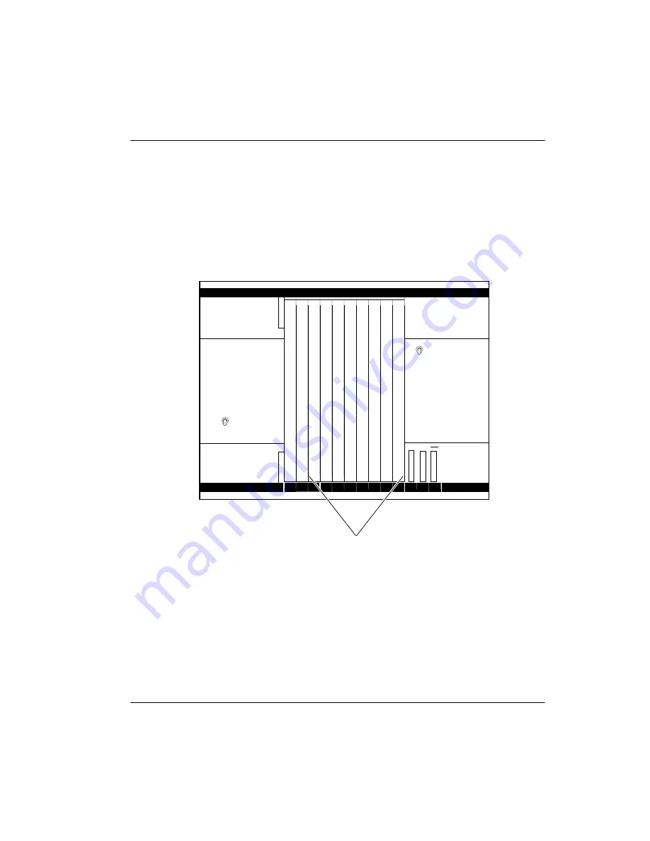
Figure 26 and Figure 27 show card placement in Option 11 systems. The cards
can be placed in slots 1 through 9 on the system shelf, as shown in Figure 26,
or in an expansion cabinet, as shown in Figure 27. Option 11 systems that are
not using Meridian Mail can also install a Companion card in slot 10. The
illustrations indicate the kinds of cards that can be included in the Option 11
system.
Figure 26: Option 11 Meridian Companion card configuration—Main cabinet
Pwr Sup
0
1
2
3
4
5
6
7
8
9
10
CPU
MM2
CMRCs/CMLCs/CMBCs
Meridian Mail
power supply
NTAK04
AC/DC or
NTAK05 DC
power supply
NTAK01
MM1
MM3
CPU
DVP
PWR
DSK
CMCC
Summary of Contents for Meridian 1 PC Console Interface Unit
Page 2: ......
Page 10: ...Page x of x 553 3601 200 Standard 7 00 November 1998 ...
Page 78: ...Page 68 of 220 Installing the hardware 553 3601 200 Standard 7 00 November 1998 ...
Page 82: ...Page 72 of 220 System initialization 553 3601 200 Standard 7 00 November 1998 ...
Page 108: ...Page 98 of 220 Activating wireless communications 553 3601 200 Standard 7 00 November 1998 ...
Page 128: ...Page 118 of 220 Programming user options 553 3601 200 Standard 7 00 November 1998 ...
Page 204: ...Page 194 of 220 Troubleshooting 553 3601 200 Standard 7 00 November 1998 ...
Page 230: ...Page 220 of 220 Index 553 3601 200 Standard 7 00 November 1998 ...
Page 231: ......


