ONL773LW3
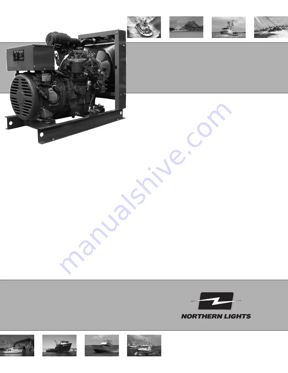
For Model: NL773LW3
OPERATOR’S MANUAL
Marine Generators | Marine Diesel Engines | Land-Based Generators
Page 1: ...ONL773LW3 For Model NL773LW3 OPERATOR S MANUAL Marine Generators Marine Diesel Engines Land Based Generators...
Page 2: ...13 As of January 2008 U S EPA regulations require the application of a permanently applied label near the fuel tank fill port for diesel driven equipment This label is to state LOW OR ULTRA LOW SULFU...
Page 3: ...SERVICING Lubrication General 14 Checking Oil 14 Oil Changes 14 Changing Oil Filter 14 Air Filter 15 V Belts 15 Valve Clearances 15 Fuels General 16 Fuel Filters 16 Bleeding the Fuel System 17 Inject...
Page 4: ...chanic Its aim is to aid you in maintaining your unit properly Introduction W NL Northern Lights industrial generator set Model number of engine block Bore Cylinders 77 mm 3 Serial Numbers MODELS INCL...
Page 5: ...signs in good and clean condition Replace missing or damaged signs Be sure new equipment components and repair parts include the current safety signs For replacement signs proper placement of safety s...
Page 6: ...all moving parts have stopped before making any adjustments connections or performing any other type of service to the engine or other driven equipment Prevent accidental discharge of starting fluids...
Page 7: ...trolyte is poisonous and strong enough to burn skin eat holes into clothing and other materials and cause blindness if splashed into eyes To Avoid Hazards Fill batteries only in well ventilated areas...
Page 8: ...d Dispose of paint and solvent properly Service Cooling System Safely WARNING Opening a pressurized cooling system can release explosive fluids and causing serious burns Before opening any pressurized...
Page 9: ...water source components between the high pressure fuel pump and nozzles on engines with high pressure fuel systems ONLY AUTHORIZED TECHNICIANS CAN PERFORM REPAIRS ON AN HIGH PRESSURE FUEL INJECTION S...
Page 10: ...t be achieved at the local supply valve shut off valves further back in the system and re check the bleed off point until complete shut off is achieved Affix a DO NOT OPERATE tag to each valve handle...
Page 11: ...Alternator 17 Radiator Shroud 1 Junction Box 2 Air Filter 3 Crankcase Vent 4 Lube Oil Fill 5 Coolant Fill 6 Injection Pump Figures 2 A and B NL773LW3 7 Fuel Lift Pump 8 Dipstick 9 Fuel Inlet and Retur...
Page 12: ...switch ON for too long can burn out the glow plugs NOTE Three position Engine Control switches must be in the RUN position during preheating Preheat switch must be held in ON position during starting...
Page 13: ...any fuel valves NOTE The battery switch must always be kept ON while the engine is running If the switch is turned OFF while the engine is running the battery charging regulator could be ruined STARTI...
Page 14: ...ses above 230 F 110 C on Industrial sets Repeat trouble shooting 3 If shutdown is activated and the temperature gauge shows temperature within normal temperature range a Check the engine crankcase oil...
Page 15: ...engine SP5 Check V belt tension SP7 Check primary fuel filter SP13 Check coolant level SP18 Check electrolyte in batteries AFTER FIRST 50 HOURS SP2 3 Change engine oil and filter SP6 Adjust valves AF...
Page 16: ...tion change oil every 100 hours or six weeks whichever comes first 4 Change oil at any seasonal change in temperature when a new viscosity of oil is required 5 Change oil when engine is warm 6 Dispose...
Page 17: ...e cylinder head bolts have been re tightened Engine should be cold and NOT running 3 Watch the valves while turning the engine over by hand Turn until the inlet valve starts to open and the exhaust va...
Page 18: ...commended The petroleum part of the biodiesel blend must meet ASTM D975 or EN590 EU specifications Biodiesel blends must be used within 90 days of their manufacture When biodiesel blends are used the...
Page 19: ...system may need manual bleeding when a A new fuel filter is installed b The engine has run out of fuel c The fuel lines injection pump or any other fuel system component has been removed and installe...
Page 20: ...lines Figure 9 Remove return line nuts Figure 10 Remove return line Figure 11 Unscrew injector Figure 12 Remove and replace copper sealing washer Figure 13 Reinstall injector Torque to proper tightne...
Page 21: ...rs for bleeding e Pump hand level on fuel pump to fill lines Tighten lines at injectors Start engine and check for leaks using a piece of paper or cardboard DO NOT use hand to check for leaks SP12 INJ...
Page 22: ...in and continue flushing until water from engine drain is clear Open all drain cocks and drain completely Close drain cock and refill with recommended coolant mixture Clean fins on radiator 3 Coolant...
Page 23: ...SP 18 19 BATTERY CARE 1 Check electrolyte level every 50 hours or once per month Add distilled water to manufacturer s recommended level 2 Batteries cables and cable terminals should be checked and cl...
Page 24: ...plug connection Low battery output Check specific gravity of each battery Check electrolyte level of each battery Defective electrical system Repair or replace ground wire Starter Cranks Slowly Low b...
Page 25: ...eck injection nozzles Uneven compression pressure Check cylinder compression pressure between cylinders Engine Runs Irregularly Below normal engine temperature Remove and check thermostat or Stalls Fr...
Page 26: ...Flush cooling system Defective thermostat Remove and check thermostat Defective temperature gauge Check water temperature with thermometer and replace gauge if necessary Water pump impeller worn brok...
Page 27: ...n Replace governor spring Low Oil Pressure Low oil level Fill crankcase to proper level Improper type of oil Drain and fill crankcase with correct oil Partially plugged oil filter Replace filter Check...
Page 28: ...ONL773LW3 11 13 26 Wiring Diagrams DC Standard Ground Engine Wiring Diagram Drawing B 9852 Wiring diagrams are subject to change without notice Revised 2 1 12...
Page 29: ...L773LW3 11 13 27 Wiring Diagrams 12 Volt DC Standard Ground Engine Wiring Diagram For Northern Lights NL773LW3 with S 1B Drawing A 3170 Wiring diagrams are subject to change without notice Added 2 1 1...
Page 30: ...L773LW3 11 13 28 Wiring Diagrams 12 Volt DC Standard Ground Engine Wiring Diagram For Northern Lights NL773LW3 with S 3C Drawing A12572B Wiring diagrams are subject to change without notice Added 2 1...
Page 31: ...ONL773LW3 11 13 29 AC Engine Wiring Diagram For Northern Lights NL773LW3 Drawing B 9724C Wiring diagrams are subject to change without notice Wiring Diagrams Revised 2 1 12...
Page 32: ...ONL773LW3 11 13 30 AC Engine Wiring Diagram For Northern Lights NL773LW3 Drawing B 9723A Wiring diagrams are subject to change without notice Wiring Diagrams Added 2 1 12...
Page 33: ......
Page 34: ...4420 14th Ave NW Seattle WA 98107 Tel 206 789 3880 1 800 762 0165 www northern lights com Northern Lights and Lugger are registered trademarks of Northern Lights Inc 2013 All rights reserved Litho USA...