North Ridge Pumps Bredel 25 Manual Download Page 1

Product Specification Sheet

X-Cel House, Chrysalis Way, Langley Bridge, Eastwood, Nottinghamshire NG16 3RY 

Tel: +44 (0) 1773 302 660  |  Email: [email protected]  |  Website: www.northridgepumps.com 
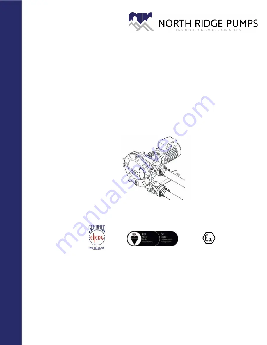
Hose pump series 

Bredel 25 and Bredel 32

Manual

Summary of Contents for Bredel 25

Page 1: ...ion Sheet X Cel House Chrysalis Way Langley Bridge Eastwood Nottinghamshire NG16 3RY Tel 44 0 1773 302 660 Email sales northridgepumps com Website www northridgepumps com Hose pump series Bredel 25 an...

Page 2: ...4 1 Identification of the product 14 4 1 1 Identification of the product 14 4 1 2 Identification of the pump 14 4 1 3 Identification of the gearbox 14 4 1 4 Identification of the electric motor 15 4 1...

Page 3: ...nt 29 7 5 Changing oil in gearbox 31 7 6 Replacing pump hose 31 7 6 1 Removing pump hose 31 7 6 2 Cleaning the pump head 34 7 6 3 Fitting the pump hose 34 7 7 Exchanging replacement parts 37 7 7 1 Rep...

Page 4: ...hims specifications 61 10 2 Lubricant table gearbox 62 10 3 Gearbox 63 10 4 Electric motor 63 10 5 Frequency controller 64 10 6 Parts list 65 10 6 1 Overview 65 10 6 2 Cover assembly 66 10 6 3 Rotor a...

Page 5: ...quency Drive VFD is normally not included in this manual However if additional documentation is supplied you must follow the instructions in this additional documentation 1 4 Service and support For i...

Page 6: ...our local government about the possibilities for reuse or environment friendly processing of packaging materials contaminated lubricant and oil CAUTION Always observe the local rules and regula tions...

Page 7: ...tions in the sales brochure In case of doubt it is the use which appears to be its intended use judging from the construction execution WARNING Procedures which if not carried out with the necessary c...

Page 8: ...ean Directive 94 9 EC ATEX Directive The pumps belong to Group II Appliances category 2 GD ck T4 2 4 Responsibility The manufacturer does not accept any responsibility for damage or harm caused by not...

Page 9: ...rsons in training may use the hose pump only under the supervision and responsibility of trained and qualified users 2 6 Regulations and instructions Everyone who works with the hose pump must be awar...

Page 10: ...rm as present in the back of this manual The safety form must be applied to the outside of the shipping carton Parts which have been contaminated or which have been corroded by chemicals or other subs...

Page 11: ...E Frequency controller option 4 1 2 Identification of the pump The identification plate on the pump head contains the following data A Pump type B Serial number C ATEX code and document number if appl...

Page 12: ...identification of the Bredel Variable Frequency Drive VFD can be found inside the VFD Remove the cover by loosening the two screws The identification sticker contains the following data A Article num...

Page 13: ...ESCRIPTION 16 4 2 Construction of the pump A Pump hose B Pump housing C Rotor D Pressing shoes E Cover F Support G Gearbox H Electric motor I Adapter without motor option J Frequency controller option...

Page 14: ...hose As soon as the pressing shoe has passed the hose recovers to its original shape due to the mechanical properties of the material In phase 2 the product is drawn into the hose by the continuous tu...

Page 15: ...edel pump hoses have been carefully machined therefore there are minimum tolerances in wall thickness It is very important to guarantee the correct compression of the pump hose because When the compre...

Page 16: ...n and cooling The pumphead in which the rotor and pump hose can be found is filled with Bredel Genuine Hose Lubricant This lubricant lubricates the movement between the hose and the pressing shoes and...

Page 17: ...y explosive atmospheres contact your Bredel representative 4 8 Available options The following options are available for the hose pump High lubricant level float switch Low lubricant level float switc...

Page 18: ...The pump materials and protective layers are suitable for indoor set up and a protected outdoor set up Under certain conditions the pump is suitable for limited outdoor set up or a salty or aggressive...

Page 19: ...s flexible hose in the suction or discharge line In this way you prevent that connection lines must be removed when changing a pump hose Keep the delivery and suction lines as short and direct as poss...

Page 20: ...the cause of the failure is removed the motor can restart automatically The automatic restart is dangerous to certain installations of the pump All control cables outside the enclosure must be shielde...

Page 21: ...ead gearbox and electric motor must be lifted using the lifting strip of the pump head plus additional support using suitably rated straps or slings A For the weights refer to 10 1 5 5 5 Placing the p...

Page 22: ...Hose Lubricant via the breather vent plug See also 7 4 3 Check the rotation of the rotor 4 Check that the correct number of shims corresponds with your application Refer to 10 1 7 For adjusting the co...

Page 23: ...otor 5 Check the capacity of the hose pump If the capacity differs from your specification follow the instructions in chapter 9 or consult your Bredel representative 6 Check the capacity range of the...

Page 24: ...NG Disconnect and lock the power supply to the pump drive before any work is carried out In case the motor is fitted with a frequency controller and has a single phase power supply wait two minutes to...

Page 25: ...a sched uled interval during oper ation In case of leakage con sult your Bredel repre sentative 4 Check pump for deviat ing temperature or strange noises On a scheduled interval during operation See...

Page 26: ...drain plug B Catch the lubricant from the pump housing in the tray Position the drain plug and tighten it firmly 12 Replacing pressing shoes Wear on the running sur face See 7 7 1 13 Replacing bearing...

Page 27: ...funnel C in the breather In order to facilitate the filling with lubricant the breather cap D on the rear of the pump housing can be removed Pour the lubricant in the pump housing via the funnel 3 Kee...

Page 28: ...plug back in the gearbox and tighten it firmly 4 Remove level plug B and filling plug C and position a funnel in the hole and fill the gearbox with oil until the oil just comes out of the level plug h...

Page 29: ...p housing in the tray Check that the breather vent mounted on the rear is not obscured Position the drain plug and tighten it firmly 4 Loosen the retaining bolts A of both the suction and discharge li...

Page 30: ...et ports 8 Slide off the sealing ring A Check that the sealing ring is not deformed or damaged and replace it if necessary Carry out this procedure both for the inlet and outlet ports 9 Switch on the...

Page 31: ...necessary Refer to 7 7 1 Also see the maintenance scheme in 7 2 6 Replace the cover and fasten the retaining bolts with the correct torque Refer to 10 1 6 7 Switch on the electrical supply to the pump...

Page 32: ...or damaged and replace it if necessary 5 Before fitting check that the hose clamp is not damaged and replace it if necessary Slide the flange bracket B and the hose clamp C over the hose together Ali...

Page 33: ...nt may leak 7 Turn the rotor in such a way that the hose A is pressed firmly against the flange surface B 8 Now fully tighten the retaining bolts A of the flange bracket B Make sure the bolts are tigh...

Page 34: ...replacement parts 7 7 1 Replacing pressing shoes 1 Jog the motor until the pressing shoe B is positioned between the inlet and outlet port A 2 Isolate the pump from the electrical supply 3 Place a tra...

Page 35: ...he Nord Lock rings D have been positioned correctly and tighten the retaining bolt s A a few turns Refer to 10 1 6 7 Check the gasket C for damage and replace if necessary Refit the cover B Make sure...

Page 36: ...12 Refill the lubricant Refer to 7 4 7 7 2 Replacing seal ring bearings and wear ring 1 Remove the pump hose Refer to 7 6 1 2 Isolate the pump from the electrical supply 3 Remove the cover B by loose...

Page 37: ...bars behind the recesses B in the rotor and push the rotor from the hub 7 Dismount the retaining circlip A with the correct tool 8 Dismount the bearings A with the correct tool the spacer ring B and...

Page 38: ...ring seat or other parts 12 Turn the rotor over Make sure that the seats of the new wear ring A and rotor are clean dry and free of grease Apply Loctite type 641 or 603 both on the rotor and the wear...

Page 39: ...heck that the Nord Lock rings D have been positioned correctly and tighten the retaining bolt s A a few turns Refer to 10 1 6 17 Check the gasket C for damage and replace if necessary Refit the cover...

Page 40: ...en the inlet and outlet port A 2 Isolate the pump from the electrical supply CAUTION Too many shims this means a too high compression force on the pump hose will create a too high load on the pump hea...

Page 41: ...the shims C or remove them until the correct number of shims is present Refer to 10 1 7 Fasten the retaining bolt of the pressing shoe with the correct torque Refer to 10 1 6 6 Refit the cover B Check...

Page 42: ...t via the breather Refer to 7 4 7 9 Fitting options 7 9 1 Fitting a high level float switch 1 Dismount the standard breather B on the rear of the pump by dismounting it from crimp connector A 2 Slide...

Page 43: ...closed NC The knob is upwards for normally closed operation When the lubricant level is too high the contact will open Specifications For use in non explosive atmospheres Voltage Max 230 V AC DC Curr...

Page 44: ...ead Position the quick couplings C and D in both openings Clamp both connection tubes E and F on the riser pipe G and the quick links C D 3 Connect the high and low level float switch to the electrica...

Page 45: ...torque of 25 Nm 2 Dismount stop A which is on the horizontal centre line at the rear of the pump housing Check that the sealing ring B is not damaged and replace it if necessary 3 Fit the stop with th...

Page 46: ...MAINTENANCE 49 5 Make sure the lubricant returns to the prescribed level Refer to 7 4 Specifications For use in non explosive atmospheres Voltage 10 30 VDC Current Max 150 mA...

Page 47: ...protection or packaging means After a long period of standstill or storage the static load on the pump hose may have caused permanent deformation which will reduce the life of the pump hose To preven...

Page 48: ...roller and has a single phase power supply wait two minutes to make sure that the capacitors have discharged Problem Possible cause Correction Failure to operate No voltage Check that the supply power...

Page 49: ...the maxi mum temperature range of the product Internal friction on the hose caused by blocked or poor suction characteristics Check pipework valves for blockages Ensure that the suction pipework is a...

Page 50: ...on side Ensure that the suction line is clear of blockages and that sufficient product is available Connections and hose clamps not correctly mounted which makes the pump suck air Tighten connections...

Page 51: ...ameter of the suction discharge lines Short hose life Chemical attack of the hose Check the compatibility of the hose material with the product to be pumped Consult your Bredel repre sentative for cor...

Page 52: ...t Hose blocked by an incom pressible object in the hose The hose cannot be compressed and will be pulled into the pump hous ing Remove hose check for blockages and replace if necessary Bolts of flange...

Page 53: ...Max capacity intermittent m3 h Intermittent duty Let the pump stand still to cool down for at least 1 hour after 2 hours of operation 2 88 5 25 Capacity per revolution l rev 0 300 0 625 Max permissibl...

Page 54: ...r Cast iron 4 Pressing shoe Aluminium 5 Pump support Mild steel galvanised 6 Flange bracket Mild steel galvanised 7 Mounting material of pump cover Mild steel galvanised 8 Mounting material of drive s...

Page 55: ...galvanised parts have been provided with an electrolytic zinc layer of 15 20 microns 10 1 4 Lubricant table pump Bredel Genuine Hose Lubricant is registered at NSF NSF Registration No 123204 Category...

Page 56: ...5 52 Stainless steel insert 2x 0 26 0 36 Hose 2 3 Lubricant 2 5 4 4 Sub total pump head 47 5 71 8 Pump support 5 7 7 1 Mounting material TWK pump head 0 3 0 3 Gearbox model B3 B5 15 5 21 Electric moto...

Page 57: ...IFICATIONS 60 10 1 6 Torque figures Pos Description Torques Nm Bredel 25 Bredel 32 A Pressing shoe 50 50 B Cover 50 50 C Hose clamp 25 25 D Flange bracket 50 50 E Support 25 85 F Gearbox 25 50 D C E A...

Page 58: ...SPECIFICATIONS 61 10 1 7 Shims specifications When the product temperatures are above 60 C always use one shim less than indicated in the diagrams Always round up the number of shims...

Page 59: ...0 C to 80 C 30 C to 60 C DIN ISO CLP CC CLP HC CLP HC ISO NLGI VG220 VG220 VG150 Mobil Mobilgear 630 Mobil SHC 630 Mobil SHC 629 Shell Shell Omala 220 Shell Omala 220 HD Kl ber Kl beroil GEM 1 220 Kl...

Page 60: ...of the recommended lubricants contact your Bredel representa tive For use in the foodstuffs industry Meets the requirements of the USDA United States Department of Agriculture lubricant is suited for...

Page 61: ...grated RFI filter B industrial applications Control Rotary knob for setting the speed and the keys for starting forward stop and starting reverse Protection class IP65 Mains power supply There are 3 t...

Page 62: ...6 1 Overview Pos Description 1 Cover assembly Refer to 10 6 2 2 Rotor assembly Refer to 10 6 3 3 Pump housing assembly Refer to 10 6 4 4 Pump support assembly Refer to 10 6 5 5 Flange assembly Refer t...

Page 63: ...Bredel 32 1 4 Bolt hex head F101058 F101058 2 4 Washer F322013 F322013 3 1 Sticker 225238 232238 4 1 Cover 225102 232102 5 1 Quad ring 225123 232123 6 1 Gasket F342019 F342019 7 1 Drain cap F911502 F9...

Page 64: ...pump type Bredel 25 Bredel 32 1 2 Pressing shoe 225110 232110 2 14 Shim 225107 10 232107 3 4 Spiral clamping bush F415084 F415084 4 2 Bolt hex head F101060 F101060 5 2 Nord Lock ring F349006 F349006 6...

Page 65: ...025070 032070 1 EPDM 025075 032075 2 1 Pump housing 225101 232101 3 1 Lifting strip 29065361 29065361 4 1 Washer Spring Lock F336012 F336012 5 1 Bolt F111096 F111096 6 4 Gasket F342027 F342027 7 3 Sto...

Page 66: ...1 16 1 Retaining circlip F343049 F343049 Pos Qty Description Product codes for parts of pump type Bredel 25 Bredel 32 1 4 Bolt F111076 F101080 2 4 Washer F322012 F322015 3 1 Pump support standard 2251...

Page 67: ...2197 2 Flange bracket SS 225197A 232197A 3 4 Washer Spring Lock F336012 F336012 4 4 Bolt F111096 F111096 5 2 Hose clamp C122004 C121006 6 2 Flange DIN Steel 025198 032198 2 Flange DIN SS 225199 232199...

Page 68: ...25 Bredel 32 1 1 Gasket F342027 F342027 2 1 Revolution counter 29040462 29040462 3 1 Adapter 29027248 29027248 Pos Qty Description Product codes for parts of pump type Bredel 25 Bredel 32 1 2 2 l can...

Reviews: