Chapter 11 – Installing the power supply
Page 91 of 536
Option 11C Compact
Planning, Installation, Fault Clearing and CCBR Guide
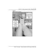
Figure 19
NTMW11 power supply switch settings
Example:
The setting for North America is
normally:
-150V for message waiting
and
86VRMS 20 Hz for ringing
SW1 SW2 SW3
SW4
ON
OFF
Message
Waiting
-150V
-120V
OFF
OFF
OFF
ON
OFF
OFF
OFF
OFF
ON
OFF
OFF
ON
Ringing
86VRMS
80VRMS
75VRMS
70VRMS
50 Hz
25 Hz
20 Hz
Frequency Setting
Switches located at top inside unit
Set switch in lower position for ON
4 3 2 1
OFF
ON
Unseat unit to set switches
Summary of Contents for Meridian Meridian 1
Page 3: ...553 3121 210 Standard 3 0 January 1999 ...
Page 17: ...xiv Contents 553 3121 210 Standard 3 0 January 1999 ...
Page 97: ...Page 78 of 536 Chapter 8 Installing a new system 553 3121 210 Standard 3 0 January 1999 ...
Page 107: ...Page 88 of 536 Chapter 10 Installing the system ground 553 3121 210 Standard 3 0 January 1999 ...
Page 113: ...Page 94 of 536 Chapter 11 Installing the power supply 553 3121 210 Standard 3 0 January 1999 ...
Page 125: ...Page 106 of 536 Chapter 12 Adding an expansion cabinet 553 3121 210 Standard 3 0 January 1999 ...
Page 209: ...Page 190 of 536 Chapter 18 Connecting the trunks 553 3121 210 Standard 3 0 January 1999 ...
Page 323: ...Page 304 of 536 Chapter 21 Installing Hospitality 553 3121 210 Standard 3 0 January 1999 ...
Page 419: ...Page 400 of 536 Chapter 23 Pre programmed data 553 3121 210 Standard 3 0 January 1999 ...
Page 555: ...Page 536 of 536 Chapter 25 Fault locating and clearing 553 3121 210 Standard 3 0 January 1999 ...

