background image

2001 Nordson Corporation

All rights reserved

334 627B

Issued 3/01

Manual 31-46

Nordson Corporation welcomes requests for information, comments and inquiries about its products.  General

information about Nordson can be found on the Internet using the following address:  http://www.nordson.com.

Address all correspondence to:

Nordson Corporation

Attn: Customer Service

555 Jackson Street

Amherst, OH 44001

Notice

This is a Nordson Corporation publication which is protected by copyright.  Original copyright date 2000.  

No part of this document may be photocopied, reproduced, or translated to another language without the prior written

consent of Nordson Corporation.  The information contained in this publication is subject to change without notice.

Trademarks

AccuJet, AquaGuard, Asymtek, Automove, Autotech, Blue Box, CF, CanWorks, Century, Clean Coat, CleanSleeve,

CleanSpray, Compumelt, Control Coat, Cross-Cut, Cyclo-Kinetic, Dispensejet, DispenseMate, Durafiber, Durasystem,
Easy Coat, Easymove Plus, Econo-Coat, EPREG, ETI, Excel 2000, Flex-O-Coat, FlexiCoat, Flexi-Spray, Flow Sentry,

Fluidmove, Fluidshooter, FoamMelt, FoamMix, Helix, Horizon, Hose Mole, Hot Shot, Hot Stitch, Isocoil, Isocore, Iso-Flo, JR,

KB30, Little Squirt, Magnastatic, MEG, Meltex, MicroSet, Millenium, Mini Squirt, Moist-Cure, Mountaingate, MultiScan,

Nordson, OmniScan, Opticoat, Package of Values, PluraFoam, Porous Coat, PowderGrid, Powderware, Pro-Flo, ProLink,

Pro-Meter, Pro-Stream, PRX, RBX, Ready Cost, Rhino, S. design stylized, Saturn, SC5, SCF, Select Charge, Select Coat,

Select Cure, Shur-Lok, Slautterback, Smart-Coat, Spray Squirt, Spraymelt, Super Squirt, Sure-Bond, Sure Coat, System

Sentry, Tela-Therm, Trends, Tribomatic, UniScan, UpTime, Veritec, Versa-Coat, Versa-Screen, Versa-Spray, Watermark, and

When you expect more. are registered trademarks of Nordson Corporation.

ATS, Auto-Flo, AutoScan, BetterBook, Chameleon, CanNeck, Check Mate, CPX, Control Weave, Controlled Fiberization,
EasyClean, Ebraid, Eclipse, Equi

=

Bead, Fillmaster, Gluie, Ink-Dot, Kinetix, Maxima, MicroFin, Minimeter, Multifil, OptiMix,

Pattern View, PluraMix, Primarc, Prism, Process Sentry, PurTech, Pulse Spray, Seal Sentry, Select Series, Sensomatic,

Shaftshield, Spectral, Spectrum, Sure Brand, Swirl Coat, Vista, Walcom, and 2 Rings (Design)

are trademarks of Nordson Corporation.

Viton is a registered trademark of DuPont Dow Elastomers.

Summary of Contents for Sure Coat Series

Page 1: ...Sure Coat Automatic Powder Spray Gun Customer Product Manual Part 334 627B NORDSON CORPORATION AMHERST OHIO USA ...

Page 2: ...pray Flow Sentry Fluidmove Fluidshooter FoamMelt FoamMix Helix Horizon Hose Mole Hot Shot Hot Stitch Isocoil Isocore Iso Flo JR KB30 Little Squirt Magnastatic MEG Meltex MicroSet Millenium Mini Squirt Moist Cure Mountaingate MultiScan Nordson OmniScan Opticoat Package of Values PluraFoam Porous Coat PowderGrid Powderware Pro Flo ProLink Pro Meter Pro Stream PRX RBX Ready Cost Rhino S design styliz...

Page 3: ...ersonal Safety 1 2 6 Fire Safety 1 2 7 Grounding 1 3 8 Action in the Event of a Malfunction 1 4 9 Disposal 1 4 1 Introduction 2 1 Features 2 1 Gun Lengths 2 1 2 Theory of Operation 2 2 3 Specifications 2 3 Electrical Output 2 3 Air Pressure Requirements 2 4 Air Quality Requirements 2 4 Equipment Rating 2 4 Dimensions 2 4 1 Mounting 3 1 2 Connections 3 3 Section 1 Safety Section 2 Description Secti...

Page 4: ... 4 Pin Functions 5 4 Continuity Across the Cable 5 5 Continuity at the Controller End 5 5 Gun Resistance and Continuity Checks 5 6 Gun Resistance 5 6 Multiplier Assembly Resistance 5 7 Electrode Support Assembly Continuity 5 8 1 Removal from the Gun Mount 6 1 2 Powder Path Repair 6 3 Disassembling the Powder Path 6 3 Inspecting and Cleaning the Powder Path 6 3 Assembling the Powder Path 6 4 3 Mult...

Page 5: ...rights reserved 334 627B Issued 3 01 Manual 31 46 1 Introduction 7 1 Using the Illustrated Parts List 7 1 2 Spray Gun Part Numbers 7 2 3 Spray Gun Parts 7 3 4 Mounting Assembly 7 6 5 Optional Nozzle 7 7 6 Cable Kits 7 7 7 O ring Kit 7 7 Section 7 Parts ...

Page 6: ...Table of Contents iv 2001 Nordson Corporation All rights reserved 334 627B Issued 3 01 Manual 31 46 ...

Page 7: ... 2000 Nordson Corporation All rights reserved Issued 7 00 S1EN 03 SF Powder 6 Section 1 Safety ...

Page 8: ...Safety 1 0 2000 Nordson Corporation All rights reserved Issued 7 00 S1EN 03 SF Powder 6 ...

Page 9: ...ns and are physically capable of performing their assigned tasks Use of Nordson equipment in ways other than those described in the documentation supplied with the equipment may result in injury to persons or damage to property Some examples of unintended use of equipment include using incompatible materials making unauthorized modifications removing or bypassing safety guards or interlocks using ...

Page 10: ...g electrical equipment Obtain and read Material Safety Data Sheets MSDS for all materials used Follow the manufacturer s instructions for safe handling and use of materials and use recommended personal protection devices To prevent injury be aware of less obvious dangers in the workplace that often cannot be completely eliminated such as hot surfaces sharp edges energized electrical circuits and m...

Page 11: ...ted to ground with a resistance of not more than 1 megohm as measured with an instrument that applies at least 500 volts to the circuit being evaluated Equipment to be grounded includes but is not limited to the floor of the spray area operator s platform hoppers photoeye supports and metal blow off nozzles Personnel working in the spray area must be grounded There is a possible ignition potential...

Page 12: ...ceive even a slight electrical shock or notice static sparking or arcing shut down all electrical or electrostatic equipment immediately Do not restart the equipment until the problem has been identified and corrected If a system or any equipment in a system malfunctions shut off the system immediately and perform the following steps Disconnect and lock out electrical power Close pneumatic shutoff...

Page 13: ... 2001 Nordson Corporation All rights reserved 334 627B Issued 3 01 Manual 31 46 Section 2 Description ...

Page 14: ...Description 2 0 2001 Nordson Corporation All rights reserved 334 627B Issued 3 01 Manual 31 46 ...

Page 15: ...ough powder path which minimizes surfaces for impact fusion to occur The rigid powder tube and all powder path components are easy to inspect clean and remove The negative polarity integral power supply voltage multiplier is user replaceable All spray guns are equipped with gun air to prevent powder from collecting on the electrode The quick disconnect inlet connector 1 allows the operator to quic...

Page 16: ... an electrode in the nozzle 3 and the grounded part in front of the spray gun The electrostatic field produces a corona discharge around the electrode Flow rate air pressure pumps the powder from the feed hopper through the feed hose into the inlet connector 1 and out through the spray gun s nozzle As the powder particles are sprayed past the electrode in the nozzle they pick up an electrostatic c...

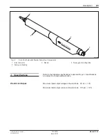
Page 17: ...Spray Gun Components 1 Inlet connector 2 Spray gun housing 3 Nozzle 4 Spray gun mounting tube Refer to the following specifications to operate the gun Specifications are subject to change without notice Maximum rated output voltage at the electrode 95 kV 10 Maximum rated output current at the electrode 100 µA 10 3 Specifications Electrical Output ...

Page 18: ...g in the pump s venturi throat powder feed hose or gun powder path Use 3 micron filter separators with automatic drains and a refrigerated or regenerative desiccant type air dryer that can produce a 3 4 C 38 F or lower dewpoint at 7 bar 100 psi This equipment is rated for use in an explosive environment Class II Division I See Figure 2 2 3146024B 1673 35 mm 65 88 in 1368 55 mm 53 88 in 7 70 cm 3 0...

Page 19: ... 2001 Nordson Corporation All rights reserved 334 627B Issued 3 01 Manual 31 46 Section 3 Installation ...

Page 20: ...Installation 3 0 2001 Nordson Corporation All rights reserved 334 627B Issued 3 01 Manual 31 46 ...

Page 21: ...bly listed in the Parts section to mount the spray gun See Figure 3 1 1 Secure the mounting bar clamp 2 on a 25 4 mm 1 in diameter bar 1 Tighten the handle 7 2 Slide the gun cable air tubing and gun mounting tube 6 through the clamp body 5 Tighten the clamping screw 4 using a 6 mm hex wrench 3 Insert the gun cable and air tubing into the hose support bracket 3 and slide the bracket onto the gun mo...

Page 22: ...ll rights reserved 334 627B Issued 3 01 Manual 31 46 3146025B 4 1 2 5 6 7 3 Fig 3 1 Spray Gun Mounting 1 25 4 mm 1 in dia bar 2 Mounting bar clamp 3 Hose support bracket 4 Clamping screw 5 Clamp body 6 Gun mounting tube 7 Handle 1 Mounting contd ...

Page 23: ...an 16 m 50 ft long See Figure 3 2 NOTE Two inlet connector barbed fittings are shipped with the gun a 1 2 in fitting attached to the spray gun and an 11 mm fitting shipped loose Select the correct fitting based on the size of feed hose in your system 1 Install the powder feed hose a Unscrew the inlet connector nut 8 and remove the nut and barbed fitting 9 from the inlet connector body 10 b Slide t...

Page 24: ...he three pin end of the gun cable to the gun cable connector 5 using the following steps a Slide back the brass lock nuts on the gun cable and the gun extension cable b Line up the pins and plug the gun cable into the gun extension cable c Screw the two brass lock nuts together Securely tighten the lock nuts 7 Secure the powder feed hose s air tubing and gun cable to the hose support bracket using...

Page 25: ...Flow rate air connector 2 Atomizing air connector 3 Gun air connector 4 Gun air coupling 5 Gun cable connector 6 Powder feed hose 7 Hose clamp 8 Inlet connector nut 9 Inlet connector barbed fitting 10 Inlet connector body 11 Gun receptacle Note Typical gun and modular gun control system shown Refer to the controller manual for specific installation instructions ...

Page 26: ...Installation 3 6 2001 Nordson Corporation All rights reserved 334 627B Issued 3 01 Manual 31 46 ...

Page 27: ... 2001 Nordson Corporation All rights reserved 334 627B Issued 3 01 Manual 31 46 Section 4 Operation ...

Page 28: ...Operation 4 0 2001 Nordson Corporation All rights reserved 334 627B Issued 3 01 Manual 31 46 ...

Page 29: ...er system components WARNING Do not operate the spray gun if the resistance of the multiplier or electrode assembly are not within the ranges specified in the Troubleshooting section Failure to observe this warning may result in personal injury fire and property damage Use the following procedure to start operating the spray gun NOTE Refer to the Operation section of the appropriate controller man...

Page 30: ...e system the powder feed center purges the spray gun internally during the color change process See Figure 4 1 In a quick color change system two powder feed hoses are used for each gun one for light colored powders and one for dark colored powders The hose hanger bracket 2 has fittings 5 on either side to hold either inlet connector with powder feed hose attached After the purge process has been ...

Page 31: ...bracket 3 Nut 4 Inlet connector powder feed hose assembly 5 Hose hanger bracket fitting Use the following procedure to shut down the gun 1 Turn off the main power switch on the controller 2 Turn off the flow rate and atomizing air pressures at the controller 3 Ground the gun electrode to discharge any residual voltage 4 Perform the daily maintenance procedure 4 Shutdown ...

Page 32: ... the gun into the powder pump 2 Unscrew the nozzle nut 5 3 Pull the nozzle 4 off the spray gun with a slight twisting motion 4 Pull the electrode support 3 straight out of the spray gun 1 The powder feed tube 2 will come out with the electrode support 5 Clean all parts with a low pressure air gun Wipe the parts with a clean dry cloth 6 Carefully remove fused powder from the parts with a wooden or ...

Page 33: ...t tightened gaps may appear between parts allowing for powder to build up and cause contamination during color changes 8 Assemble the gun Tighten the inlet connector body at the back of the gun to ensure that there are no gaps between the powder path components Check the resistance of the multiplier and resistor assembly with a megohm meter as described in the Troubleshooting section Replace the m...

Page 34: ...Operation 4 6 2001 Nordson Corporation All rights reserved 334 627B Issued 3 01 Manual 31 46 ...

Page 35: ... 2001 Nordson Corporation All rights reserved 334 627B Issued 3 01 Manual 31 46 Section 5 Troubleshooting ...

Page 36: ...Troubleshooting 5 0 2001 Nordson Corporation All rights reserved 334 627B Issued 3 01 Manual 31 46 ...

Page 37: ...ng charts to troubleshoot the spray gun Problem Possible Cause Corrective Action 1 Uneven pattern unsteady or inadequate powder flow Low atomizing or flow rate air pressure Increase the atomizing and or flow rate air pressures Blockage in the gun powder feed hose or pump 1 Disconnect the powder feed hose from the pump 2 Blow out the hose with compressed air 3 Disassemble the gun and pump and clean...

Page 38: ...rn nozzle Remove and inspect the nozzle Replace it if it is worn Plugged powder path Remove the nozzle parts inlet connector and powder feed hose from the gun and clean them 3 Loss of wrap poor transfer efficiency NOTE Before checking possible causes check the error code on the controller and perform the error code corrective action in the controller manual Low electrostatic voltage Increase the e...

Page 39: ...e controller manual Damaged gun cable Error codes 7 or 8 Perform the Gun Cable Checks in this section If an open or short is found replace the cable Malfunctioning controller If you found no problem with the gun cable refer to the Troubleshooting section of the controller manual Malfunctioning multiplier Error codes 7 or 8 Perform the Multiplier Assembly Resistance procedure in this section Poor e...

Page 40: ...uidelines to check the continuity of the gun cable Make the continuity checks with a standard ohm meter Pin Functions Refer to Tables 5 1 and 5 2 and see Figure 5 1 for descriptions of the pin functions Table 5 1 Pin Functions Controller End J1 Pin Function 1 Blank no pin 2 Common 3 Vdc 4 µA feedback 5 Blank no pin 6 Ground gun and cable shield 7 Gun ID 8 Gun ID Table 5 2 Pin Functions Gun End J2 ...

Page 41: ...D GUN ID A 200 COMMON VDC FDBK A CHASSIS GND Fig 5 1 Gun Cable Pins Continuity Across the Cable Refer to Table 5 3 and see Figure 5 1 for a list of continuity checks to perform across the cable Table 5 3 Continuity Checks Across the Cable J1 Pin Controller End J2 Pin Gun End 2 3 3 1 4 2 Continuity at the Controller End See Figure 5 1 Perform the following resistance and continuity checks at the co...

Page 42: ...nector 2 3 Connect the megohm meter 4 probes to the shorting plug ring tong terminal and gun electrode 3 If the reading is infinite reverse the probes 4 Check the megohm meter reading Resistance should be between 150 and 220 MΩ at 500 Volts 5 If the reading is not between 150 and 220 MΩ perform the Multiplier Assembly Resistance and Electrode Assembly Resistance procedures in this section 3146006B...

Page 43: ...on 2 Connect the shorting plug connector 1 to the multiplier connector 2 3 Connect the megohm meter probes to the shorting plug ring tong terminal and tip of the multiplier assembly 3 If the reading is infinite reverse the probes 4 Check the megohm meter reading Resistance should be between 150 and 220 MΩ at 500 Volts 5 If the reading is not between 150 and 220 MΩ check the multiplier assembly for...

Page 44: ...ssembly See Figure 5 4 1 Remove the electrode support assembly from the gun Refer to Disassembling the Powder Path in the Repair section 2 Connect a standard ohmmeter s probes to the contact wire 1 and tip of the electrode 2 3 If there is not continuity unscrew the electrode holder and check for burn through or arc tracks around the contact wire Check the electrode spring to make sure it is not br...

Page 45: ... 2001 Nordson Corporation All rights reserved 334 627B Issued 3 01 Manual 31 46 Section 6 Repair ...

Page 46: ...Repair 6 0 2001 Nordson Corporation All rights reserved 334 627B Issued 3 01 Manual 31 46 ...

Page 47: ...cing Failure to observe this warning may result in personal injury or death Use the following procedures to remove the gun from the mounting assembly NOTE Refer to Mounting in the Installation section for instructions for installing the gun and mounting assembly after repairs See Figure 6 1 1 Unscrew the inlet connector nut 6 and pull the inlet connector powder feed hose assembly 5 from the inlet ...

Page 48: ...d 3 01 Manual 31 46 3146027B 4 3 2 1 5 6 8 7 Fig 6 1 Removal from the Gun Mount 1 Spray gun 2 Handle 3 Gun bar clamp 4 Inlet connector body 5 Inlet connector powder feed hose 6 Inlet connector nut 7 Gun air coupling 8 Gun cable extension 1 Removal from the Gun Mount contd ...

Page 49: ...th the electrode support assembly 3 Unscrew the inlet connector body 1 from the spray gun 1 Clean all parts with a low pressure air gun Wipe the parts with a clean dry cloth 2 Carefully remove fused powder from the parts with a wooden or plastic dowel or similar tool Do not use tools that will scratch the plastic Powder will build up and impact fuse on scratches NOTE If necessary use a cloth dampe...

Page 50: ...he assembly into the spray gun making sure that the long electrode support key slot is facing upward NOTE When you install the nozzle there will be a gap between the base of the nozzle and the front of the gun Rotate the nozzle at least 90 from its previous position to prevent uneven wear and lopsided patterns 3 Install the nozzle 5 and nozzle nut 6 4 Install the inlet connector body 1 onto the ba...

Page 51: ...rdson Corporation All rights reserved 334 627B Issued 3 01 Manual 31 46 3146012B 1 3 4 5 2 6 Fig 6 2 Powder Path Repair 1 Inlet connector 2 Spray gun 3 Powder feed tube 4 Electrode support assembly 5 Nozzle 6 Nozzle nut ...

Page 52: ...l not to lose the tension tube locator 3 when you separate the body from the mounting tube c Carefully separate the body 14 from the mounting tube 4 d Unscrew the gun cable extension 7 and disconnect the gun air tubing extension 6 from the mounting bracket 10 e Unscrew the tension tube and remove it from the mounting bracket 3 Remove the screws 8 and O rings 9 securing the mounting bracket to the ...

Page 53: ...0 4 14 6 5 3 2 8 11 12 13 Fig 6 3 Multiplier Replacement 1 Inlet connector powder feed tube 2 Lock nut 3 Tension tube locator 4 Mounting tube 5 Tension tube 6 Gun air tubing extension 7 Gun cable extension 8 Screws 9 O rings 10 Mounting bracket 11 Multiplier 12 Contact assembly 13 Multiplier nut 14 Gun body ...

Page 54: ...et 10 into the gun Secure the mounting bracket using the screws 8 and O rings 9 4 Thread the tension tube 5 into the mounting bracket 5 Connect the gun cable extension 7 and air tubing extension 6 into the mounting bracket 6 Slide the tension tube and cable and gun air tubing extensions into the large end of the mounting tube 4 Push the mounting tube as far as it will go against the mounting brack...

Page 55: ... 2001 Nordson Corporation All rights reserved 334 627B Issued 3 01 Manual 31 46 Section 7 Parts ...

Page 56: ...Parts 7 0 2001 Nordson Corporation All rights reserved 334 627B Issued 3 01 Manual 31 46 ...

Page 57: ...ription column gives the part name as well as its dimensions and other characteristics when appropriate Indentions show the relationships between assemblies subassemblies and parts Item Part Description Quantity Note 000 0000 Assembly 1 1 000 000 Subassembly 2 A 2 000 000 Part 1 If you order the assembly items 1 and 2 will be included If you order item 1 item 2 will be included If you order item 2...

Page 58: ...erial number are printed onto the label on the bottom of the gun To order the correct parts for your gun match the gun part number on the label with the gun description Part Description Note 101 0699 Gun Sure Coat automatic 3 ft tube negative 101 0698 Gun Sure Coat automatic 4 ft tube negative 101 0697 Gun Sure Coat automatic 5 ft tube negative 2 Spray Gun Part Numbers ...

Page 59: ...28 Nut lock nozzle 1 11 Tube tie bar 3 ft packaged 1 B 11 Tube tie bar 4 ft packaged 1 B 11 Tube tie bar 5 ft packaged 1 B 12 940 203 O ring silicone 0 875 x 1 000 x 0 063 in 2 13 327 981 Screw cheese head recessed M4 x 25 black zinc 2 14 940 060 O ring Viton 0 125 x 0 250 x 0 063 in 2 15 972 398 Connector round male M4 tubing x M5 thread 1 16 Bracket sealing 1 17 327 979 Gasket multiplier 1 18 32...

Page 60: ...7 Tube mount 5 ft 1 B 28 100 1798 Locator tensioning tube 1 29 327 719 Nut tensioning tube mount 1 30 100 3572 Hanger hose automatic gun 1 31 101 0723 Connector hose body 1 32 101 0724 Connector hose barb 11 mm 1 32 101 0726 Connector hose barb 1 2 in 1 33 101 0725 Connector hose nut 1 NS 247 006 Clamp hose 0 673 0 795 OD 1 C NS 939 247 Clamp hose 0 781 0 875 OD 1 D NS 100 1222 Cable extension Sur...

Page 61: ...7 5 2001 Nordson Corporation All rights reserved 334 627B Issued 3 01 Manual 31 46 3146029B 1 2 7 3 4 8 9 10 15 16 17 18 22 23 31 30 26 28 27 11 12 19 5 13 14 20 21 24 6 25 25 33 32 29 Fig 7 1 Spray Gun Parts ...

Page 62: ...gun stands See Figure 7 2 Item Part Description Quantity Note 101 0717 Mounting assembly Sure Coat automatic gun 1 1 248 957 Handle adjustment 3 8 16 x 1 77 in 1 2 101 0719 Mount clamp automatic gun 1 3 101 0780 Mount sleeve automatic gun 1 4 981 561 Screw socket 3 8 16 x 1 000 in zinc 3 3146031B 1 2 3 4 Fig 7 2 Mounting Assembly 4 Mounting Assembly ...

Page 63: ...eter The following kit contains all O rings in the spray gun See Figure 7 3 Item Part Description Quantity Note 101 0753 Service kit O rings Sure Coat automatic gun 1 1 941 162 O ring silicone 0 750 x 0 937 x 0 094 in 5 5 940 060 O ring Viton 0 125 x 0 250 x 0 063 in 10 4 327 986 O ring silicone 2 063 x 2 250 x 0 094 in 5 3 941 205 O ring silicone 1 000 x 1 188 x 0 094 in 5 6 940 203 O ring silico...

Page 64: ...Parts 7 8 2001 Nordson Corporation All rights reserved 334 627B Issued 3 01 Manual 31 46 3146020B 1 4 5 6 5 3 8 7 7 2 Fig 7 3 O ring Kit 7 O ring Kit contd ...

Page 65: ...tive 94 9 EC Equipment for use in potentially Explosive Atmospheres Directive STANDARDS USED TO VERIFY COMPLIANCE EN292 EN50081 EN50014 EN50082 IEC417L EN50177 EN55011 FM7260 EN50050 EN60204 PRINCIPLES This product has been manufactured according to good engineering practice The product specified conforms to the directive and standards described above CERTIFICATIONS ISO 9001 DNV No QSC3277 EECS No...

Page 66: ......

Reviews: