background image

USER'S MANUAL

CAUTION

Read all precautions and instruc-

tions in this manual before using

this equipment. Save this manual

for future reference.

Model No. NTL10008.0

Serial No.

Write the serial number in the space

above for reference.

QUESTIONS?

If you have questions, or if parts are

damaged or missing,

DO NOT

CONTACT THE STORE; please

contact Customer Care.

IMPORTANT: You must note the

product model number and serial

number (see the drawing above)

before contacting us:

CALL TOLL-FREE:

1-888-825-2588

Mon.–Fri. 6 a.m.–6 p.m. MT

Sat. 8 a.m.–4 p.m. MT
ON THE WEB:

www.nordictrackservice.com

www.nordictrack.com

Serial Number Decal

Summary of Contents for NTL10008.0

Page 1: ...ace above for reference QUESTIONS If you have questions or if parts are damaged or missing DO NOT CONTACT THE STORE please contact Customer Care IMPORTANT You must note the product model number and se...

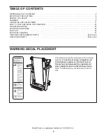
Page 2: ...AWING 27 ORDERING REPLACEMENT PARTS Back Cover LIMITED WARRANTY Back Cover NordicTrack is a registered trademark of ICON IP Inc 2 This drawing shows the location s of the warning decal s If a decal is...

Page 3: ...tension cord 12 Use only a single outlet surge suppressor that meets all of the specifications described on page 11 To purchase a surge suppressor see your local NordicTrack dealer or call the tele ph...

Page 4: ...ke sure that the storage latch is holding the frame securely in the storage position 24 Always remove iFit cards from the iFit slot when you are not using them 25 Inspect and properly tighten all part...

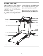
Page 5: ...e using the treadmill If you have questions after read ing this manual please see the front cover of this man ual To help us assist you note the product model number and serial number before contactin...

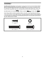
Page 6: ...e off the lubricant with a soft cloth and a mild non abrasive cleaner Assembly requires the included hex key a Phillips screwdriver and wire cutters Use the drawings below to identify the assembly har...

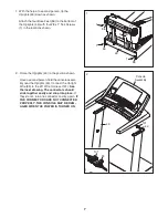
Page 7: ...ether easily and snap into place If they do not turn one connector and try again IF THE CONNECTORS ARE NOT CONNECTED PROPERLY THE CONSOLE MAY BE DAM AGED WHEN THE POWER IS TURNED ON Console Assembly 2...

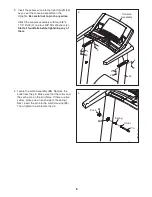
Page 8: ...3 8 Star Washers 4 Start all four Bolts before tightening any of them Console Assembly 3 4 4 2 2 4 2 4 2 43 4 Locate the Latch Assembly 88 Remove the knob from the pin Make sure that the collar and th...

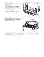
Page 9: ...l slightly as you tighten the Bolts Lower the treadmill as described on page 21 5 97 3 43 6 Make sure that the Left Accessory Tray 112 and the Right Accessory Tray 117 are pressed firmly into the cons...

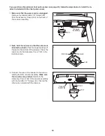
Page 10: ...y Cover 122 in the location shown 3 Connect the wire on the receiver to the wire ex tending from the console assembly Make sure that no wires are pinched Reattach the Accessory Cover 122 to the consol...

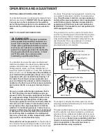
Page 11: ...tion or break down grounding provides a path of least resistance for electric current to reduce the risk of elec tric shock This product is equipped with a cord having an equipment grounding conductor...

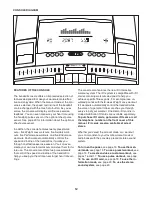
Page 12: ...mill to help you keep your heart rate near target heart rate set tings The console also features the new iFit interactive workout system The iFit system is compatible with iFit cards containing workou...

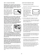
Page 13: ...can display speed and distance in either miles or kilometers To find out which unit of measurement is selected or to change the unit of mea surement see THE INFORMATION MODE on page 20 For simplicity...

Page 14: ...pulse sensor at the same time the console will not display your heart rate accurately See page 20 for information about the optional chest pulse sensor Before using the handgrip pulse sensor remove t...

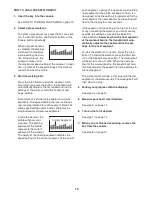
Page 15: ...segment indicates the speed setting for the current segment At the end of each segment a series of tones will sound and the next segment of the profile will begin to flash If a new speed or incline s...

Page 16: ...r each seg ment To program speed and incline settings for the first segment simply adjust the speed and in cline of the treadmill as desired by pressing the Speed and Incline buttons When the first se...

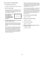
Page 17: ...workout will function in the same way as a preset workout see step 3 on page 15 If desired you can redesign the workout while using it To change the speed setting or the in cline setting for the curr...

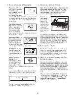
Page 18: ...will automatically increase or decrease to bring your heart rate closer to the tar get heart rate setting If your pulse is not detected during the program the letters PLS will flash in the display an...

Page 19: ...kout A mo ment after you press the button the treadmill will automatically adjust to the first speed and incline settings of the workout Hold the handrails and begin walking During the workout the voi...

Page 20: ...n you remove the key the displays will remain lit although the buttons will not function If the demo mode is turned on a d will ap pear in the Speed Calories display while the information mode is sele...

Page 21: ...ct sunlight Do not leave the treadmill in the stor age position in temperatures above 85 F 30 C HOW TO MOVE THE TREADMILL Before moving the treadmill convert the treadmill to the stor age position as...

Page 22: ...LUTION a Check the reset off circuit breaker see the drawing above If the circuit breaker has tripped wait for five minutes and then press the switch to the reset position b Make sure that the power c...

Page 23: ...elt slips when walked on first remove the key and UNPLUG THE POWER CORD Using the hex key turn both idler roller bolts clockwise 1 4 of a turn When the walking belt is correctly tightened you should b...

Page 24: ...If your goal is to strengthen your cardiovascular system you must perform aerobic exer cise which is activity that requires large amounts of oxygen for prolonged periods of time For aerobic ex ercise...

Page 25: ...ount 40 2 Idler Roller Spring 41 1 Idler Arm Spring 42 1 Hex Key 43 1 Upright 44 43 8 x 1 2 Screw 45 8 3 x 1 4 Screw 46 3 8 Star Washer 47 1 Front Left Cap 48 2 Belt Guide 49 1 Latch Plate 50 1 Magnet...

Page 26: ...1 2 Speaker 112 1 Left Accessory Tray 113 1 Console 114 1 Console Fan 115 1 Right Speaker Cover Bottom 116 1 Key Clip 117 1 Right Accessory Tray 118 1 Digital Player Tray 119 1 Left Pulse Sensor 120 1...

Page 27: ...2 22 48 48 56 49 5 51 54 61 62 7 7 24 27 42 69 63 21 65 64 66 7 8 57 59 55 18 50 53 60 12 32 40 30 67 64 68 7 21 32 33 8 26 40 30 24 24 24 26 33 33 33 47 60 9 18 EXPLODED DRAWING A Model No NTL10008 0...

Page 28: ...32 15 16 17 29 32 23 32 41 87 36 71 72 9 38 39 9 9 9 39 10 32 35 35 27 22 11 11 11 75 74 73 34 6 83 81 80 6 12 86 12 84 12 23 46 85 44 11 12 12 25 25 34 78 77 82 70 23 58 EXPLODED DRAWING B Model No...

Page 29: ...29 3 97 98 1 90 32 20 37 92 91 1 32 90 20 37 92 91 96 1 43 88 89 2 4 1 23 95 2 93 2 2 94 94 3 3 4 4 4 93 96 96 96 EXPLODED DRAWING C Model No NTL10008 0 R0109A...

Page 30: ...30 102 104 100 99 12 101 105 101 11 103 12 12 43 43 12 12 43 43 12 12 12 12 12 12 123 123 EXPLODED DRAWING D Model No NTL10008 0 R0109A...

Page 31: ...12 44 44 106 12 12 110 112 107 13 46 46 120 119 118 116 109 108 12 44 44 113 45 114 44 44 111 44 111 44 45 44 44 44 44 44 44 44 44 44 44 115 12 12 12 44 12 12 12 13 13 13 31 28 44 EXPLODED DRAWING E M...

Page 32: ...a minimal handling charge For in home service the customer will be responsible for a minimal trip charge This warranty does not extend to any damage to a product caused by or attributable to freight d...

Reviews: