background image

4. Software installation: Starting up

NORD MODULAR G2 V1.1

Page 24

S

S

S

S

T

T

T

TA

A

A

AR

R

R

RT

T

T

TIIIIN

N

N

NG

G

G

G


U

U

U

UP

P

P

P

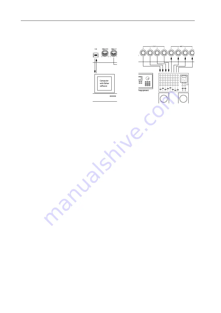
Make all the audio connections be-
fore turning on any of the devices. 
The computer that runs the Editor 
must be connected via a USB port to 
the Nord Modular G2.

S

S

S

S

O

O

O

OU

U

U

UN

N

N

ND

D

D

D


S

S

S

SY

Y

Y

YS

S

S

ST

T

T

TE

E

E

EM

M

M

M

Connect the desired outputs of the 
Nord Modular G2 to a sound sys-
tem. We suggest that you start by 
connecting output 1 to the left 
channel and output 2 to the right 
channel of the sound system. Turn 
on Nord Modular G2 first, followed 
by the sound system.

L

L

L

L

A

A

A

AU

U

U

UN

N

N

NC

C

C

CH

H

H

HIIIIN

N

N

NG

G

G

G


T

T

T

TH

H

H

HE

E

E

E

 E

 E

 E

 E

D

D

D

DIIIIT

T

T

TO

O

O

OR

R

R

R

Power on the synth and make sure the USB cable is properly connected between the synth and your com-
puter. From the Start menu in the Windows taskbar, select Programs|Nord Modular G2 V1.10|Modular 
Editor V1.10. During the start-up procedure, the Editor software will automatically search for and estab-
lish contact with the Nord Modular G2 synthesizer. If the connection between the synth and the com-
puter is not working properly, an error message will appear. In that case, check the USB cable, make sure 
that the USB driver is properly installed and working, and that the synth is turned on. When the Editor 
has found the synth, the name of the connected synth is shown in the Status line. Any Patch currently 
loaded in the focused 

S

LOT

 will automatically upload to the Editor and open in the Patch window.

U

U

U

U

P

P

P

PD

D

D

DA

A

A

AT

T

T

TIIIIN

N

N

NG

G

G

G


T

T

T

TH

H

H

HE

E

E

E

 OS 

 OS 

 OS 

 OS 

IIIIN

N

N

N


T

T

T

TH

H

H

HE

E

E

E


S

S

S

SY

Y

Y

YN

N

N

NT

T

T

TH

H

H

H

Note! If you received a brand new Nord Modular G2 or G2 Engine, the latest operating system is al-
ready installed from factory. If so, there is no need to update the synth.

If you need to update the OS in the synth, do like this:

1. Make sure the USB Driver and Editor are properly installed as described earlier in this chapter.

2. Power on the G2 synth and connect the USB cable between the synth and computer.

3. Make sure the G2 Editor is 

not

 running.

4. Open the ‘Modular Synth Updater’ in the Programs|Nord Modular G2 folder in the Start menu of 

the computer and click the Update button to complete the OS update. As the update proceeds, the 

Connecting the 
G2 to the PC

Connecting the G2 to 
the sound system

Summary of Contents for modular G2

Page 1: ...User Manu User Manu User Manu User Manu User Manual al al al al Sof Sof Sof Sof Software V tware V tware V tware V tware Version 1 1x ersion 1 1x ersion 1 1x ersion 1 1x ersion 1 1x Part No 50212...

Page 2: ...tructions importantes pour le fonctionnement et l entretien service dans le livret d instructions accompagnant l appareil Instructions pertaining to a risk of fire electric shock or injury to persons...

Page 3: ...XRouter modules described on pages 134 135 and 168 169 are not yet implemented in the system These modules will be included shortly in an upcoming software update which can be downloaded at http www c...

Page 4: ......

Page 5: ...dular G2 Engine rear panel Nord Modular G2 Engine rear panel Nord Modular G2 Engine rear panel 19 19 19 19 3 3 3 3 Synth quick tour Synth quick tour Synth quick tour Synth quick tour 20 20 20 20 Check...

Page 6: ...Bandwidth considerations 30 Self optimizing modules 30 Experiment 30 General module parameter types General module parameter types General module parameter types General module parameter types 31 31...

Page 7: ...llers 50 Morph groups Morph groups Morph groups Morph groups 51 51 51 51 Assign parameters to a Morph group 52 Deassign parameters from a Morph group 52 Edit parameters in a Morph group 53 Copy a Morp...

Page 8: ...Assign parameters to panel controls Assign parameters to panel controls Assign parameters to panel controls Assign parameters to panel controls 64 64 64 64 Patch parameter Variations Patch parameter...

Page 9: ...functions The System functions 79 79 79 79 Patch functions Pa 79 Performance functions Pe 80 System functions Sy 80 Dump One 82 9 9 9 9 Working with the Working with the Working with the Working with...

Page 10: ...ameter Pages 92 Parameter Overview 93 Virtual Keyboard 93 File Browser 94 Auto assign MIDI controllers 95 Deassign MIDI Controllers 95 Extended Toolbar 95 Window menu Window menu Window menu Window me...

Page 11: ...104 The function keys 105 10 10 10 10 MIDI implementation MIDI implementation MIDI implementation MIDI implementation 106 106 106 106 MIDI Controllers MIDI Controllers MIDI Controllers MIDI Controlle...

Page 12: ...eters 121 OscA 125 OscB 125 OscC 125 OscD 126 OscPM 126 OscShpA 126 OscShpB 128 OscDual 130 StringOsc 131 OscPerc 132 DrumSynth 132 Noise 133 OscMaster 133 Operator 134 LFO group LFO group LFO group L...

Page 13: ...151 Common Filter parameters 151 LP Filter 153 HP Filter 153 FltNord 153 FltClassic 153 FltMulti 154 FltStatic 154 WahWah 154 FltVoice 154 Vocoder 155 Eq1 156 Eq2Band 156 Eq3Band 157 FltPhase 157 Flt...

Page 14: ...Sw1 2 165 Sw1 4 165 Sw1 8 166 ValSw2 1 166 ValSw1 2 166 WindSw 166 Mux8 1 166 Mux1 8 167 Mux8 1X 167 Sample Hold 167 Track Hold 167 DXRouter 168 Level group Level group Level group Level group 169 16...

Page 15: ...181 181 181 181 Common Sequencer parameters 181 SeqEvent 182 SeqVal 183 SeqLev 183 SeqNote 183 SeqCtr 184 Sequencing examples 184 FX group FX group FX group FX group 188 188 188 188 Common FX group p...

Page 16: ...aveforms The oscillators and waveforms 202 202 202 202 Pitch 202 Waveform 203 The filter The filter The filter The filter 207 207 207 207 Filter types 208 Roll off slope 209 Cutoff frequency 210 Reson...

Page 17: ...O O OU U U UT T T T T T T TH H H HI I I IS S S S M M M MA A A AN N N NU U U UA A A AL L L L Every time this manual wants your attention to an object on the synth panel the name of that object will be...

Page 18: ...isk drives moving and closing windows closing dialog boxes etc It is also important that the computer has a free USB port and that the Nord Modular G2 USB driver has been properly installed before con...

Page 19: ...input level of the microphone connected to the XLR INPUT on the rear panel If you don t use a mic the Level LEDs will indicate the input level of the signal routed to the IN 1 input instead S S S SY Y...

Page 20: ...P P P PL L L LA A A AY Y Y Y M M M MO O O OD D D DE E E E Lets you switch between two different display modes for the AS SIGNABLE DISPLAYS By default the ASSIGNABLE DISPLAYS show module names and para...

Page 21: ...PLAYS and the Programmable Parameter Pages P P P PR R R RO O O OG G G GR R R RA A A AM M M MM M M MA A A AB B B BL L L LE E E E P P P PA A A AR R R RA A A AM M M ME E E ET T T TE E E ER R R R P P P PA...

Page 22: ...N N NO O O OR R R RD D D D M M M MO O O OD D D DU U U UL L L LA A A AR R R R G2 E G2 E G2 E G2 EN N N NG G G GI I I IN N N NE E E E F F F FR R R RO O O ON N N NT T T T P P P PA A A AN N N NE E E EL L...

Page 23: ...0 dBV audio outputs OUTPUT 1 4 route the audio signals from the four virtual mix buses in Nord Modular G2 Engine Use OUTPUT 1 if you are going to use Nord Modular G2 Engine with a mono sound system If...

Page 24: ...the ASSIGNABLE KNOBS the LED GRAPH will change and the exact value will be shown in the ASSIGNABLE DISPLAY above the knob A A A AC C C CC C C CE E E ES S S SS S S S M M M MO O O OR R R RE E E E A A A...

Page 25: ...M ME E E EM M M MO O O OR R R RY Y Y Y Load the new Patch into the active Slot Slot A in this example by first turning the ROTARY DIAL to select the Patch If you like you can also switch between Bank...

Page 26: ...mable Parameter Pages of each individual Patch hold down SHIFT and press the PATCH SETTINGS button again Now the first Parameter Page of the Patch in the focused Slot is shown in the ASSIGNABLE DIS P...

Page 27: ...ular G2 synthesizer to the PC you need to install the USB driver The USB driver makes it possible for the PC to recognize the G2 and for the Editor to communicate with the synth To install the USB dri...

Page 28: ...the connection between the synth and the com puter is not working properly an error message will appear In that case check the USB cable make sure that the USB driver is properly installed and workin...

Page 29: ...d the STORE PERFORMANCE MODE buttons and power on the synth On the G2 Engine press the hidden button inside the hole to the right of the G2 logotype and power on the synth First the MIDI LED lights up...

Page 30: ...group which have no connectors These connectors come in two different shapes circular inputs and square outputs and three different variants red audio blue control and yellow logic connec tors Most of...

Page 31: ...LO O O OT T T TS S S S There are four SLOTS labelled A B C and D on the Nord Modular G2 You can load one Patch at a time to each Slot A Slot can be considered a temporary RAM memory which can hold a...

Page 32: ...its The illustration to the right shows the levels and the polarity of the signals from the keyboard an LFO an envelope an audio signal and a logic signal The LFO is an example of a bipolar modulator...

Page 33: ...r bipolar They are used to control or modulate parameters in a Patch The control signals are 24 bit at 24 kHz sampling frequency i e a quarter of the audio signal bandwidth This is be cause they are o...

Page 34: ...an LFO is a control signal updated at quarter speed of an audio signal the quality of an LFO generated signal might not be good enough to be used as an audio signal If high audio quality is important...

Page 35: ...le to reset the knob to the default 12 o clock position S S S SL L L LI I I ID D D DE E E ER R R RS S S S A slider basically has the same functionality as a knob only a different ap pearance Sliders c...

Page 36: ...handling sig nals at full audio bandwidth or they can be blue like the Vowel modulation input of the Voice Filter module working at 1 4 au dio bandwidth The modulation inputs can also be self optimiz...

Page 37: ...e pulse width on the OscDual module as an example in two scenarios 1 If you want to modulate the pulse width from the minimum value 1 to the maximum value 99 with a positive envelope that produces a c...

Page 38: ...f you change the modulator pitch you will affect the overall pitch and if you change the oscillator pitch this will create changes in timbre rather than in pitch If you let the synchronized oscillator...

Page 39: ...Area and FX Area below The actual polyphony of a Patch is displayed in the Voice Mode display box The requested number of voices is dis played within parenthesis Should your request for polyphony exce...

Page 40: ...create a basic subtractive synthesis Patch Make sure the Editor has established contact with the synthesizer If it hasn t please see Launching the Editor on page 24 1 Select File New 2 An empty Patch...

Page 41: ...es have been properly connected no sound is heard You have to make the envelope generator open up for the audio signal This is done by simply playing the synth keyboard The KBG Keyboard Gate button on...

Page 42: ...of voices for the Patch is shown and the requested number within parenthesis In this example we request 4 voices 12 In the bottom section of the Patch window the FX Area you can place modules that sho...

Page 43: ...e Pitch modulation amount and lower the Freq amount a little Play the keyboard and notice how the filter opens up with increasing Velocity 15 Finally to make the Patch editable and controlla ble from...

Page 44: ...r G2 A new Patch window will be created in the Editor containing the Patch of the active SLOT The Patch window gets the same name as the Patch in the uploaded SLOT when saved to disk C C C CR R R RE E...

Page 45: ...s is to Shift click on the desired modules The names of the selected modules are highlight ed to indicate that they have been selected D D D DE E E EL L L LE E E ET T T TE E E E A A A A M M M MO O O O...

Page 46: ...gic signal connectors Yellow 24 bit and 24 kHz sampling frequency or Orange 24 bit and 96 kHz sampling frequency C C C CO O O ON N N NN N N NE E E EC C C CT T T TI I I IN N N NG G G G C C C CA A A AB...

Page 47: ...e right click on a connection input or output and select Disconnect or double click hold or Ctrl click on a connection an extra wire appears next to the connector cursor and pull out the connector by...

Page 48: ...e Patch e g different types of FX modules Modules used in the FX Area will act on the sum of the signals output from the Voice Area and consequently will not be duplicated for each voice in the Patch...

Page 49: ...32 with the UP DOWN NAVIGATOR buttons and a memory location 1 128 with the ROTARY DIAL Con firm by pressing STORE again Abort by pressing any other button 3 To store a Patch in Nord Modular G2 interna...

Page 50: ...rnal memory when trying to store a Patch this will be indicated by the following message in the DIS PLAY You will then have to delete one or several Patches to make room for new ones This can be done...

Page 51: ...the Sound engine has to recalculate the whole Patch the same way as if you replaced the entire module If you want to have different Oscillator or LFO waveforms in different Variations use modules with...

Page 52: ...lumns with ASSIGNABLE KNOBS of the Nord Modular G2 front panel The Parameter Pages window gives you both visual indication and the possibility to edit the parameters currently assigned to an ASSIGNABL...

Page 53: ...assignment is completed To deassign right click the knob or display box in the Parameter Pages window and select Deassign An ASSIGNABLE KNOB will always control the entire range of a parameter If you...

Page 54: ...le parameters MIDI MIDI MIDI MIDI C C C CO O O ON N N NT T T TR R R RO O O OL L L LL L L LE E E ER R R RS S S S Almost any parameter in the different modules can be assigned to a MIDI Controller This...

Page 55: ...T T TR R R RO O O OL L L LL L L LE E E ER R R RS S S S If you want to use one or several ASSIGNABLE KNOBS to exclusively transmit MIDI controller data to external devices you will need to take a detou...

Page 56: ...phed parameter within the selected range Note that the morphed knob s in the module s won t change visually 4 If you want to assign parameters to another Morph group click another Morph group knob in...

Page 57: ...S S I I I IN N N N S S S SE E E EP P P PA A A AR R R RA A A AT T T TE E E E V V V VA A A AR R R RI I I IA A A AT T T TI I I IO O O ON N N NS S S S Each Variation in a Patch can have its own unique Mo...

Page 58: ...When you upload a Performance from the synth to the Editor you replace the four Patches currently in the Slots A to D with the Patches in the Performance You also recall other settings as listed in th...

Page 59: ...er boxes C C C CO O O OM M M MB B B BI I I IN N N NI I I IN N N NG G G G S S S SP P P PL L L LI I I IT T T T A A A AN N N ND D D D L L L LA A A AY Y Y YE E E ER R R R Layering Slots simply means that...

Page 60: ...M M M A A A A P P P PE E E ER R R RF F F FO O O OR R R RM M M MA A A AN N N NC C C CE E E E The Patches used in the Slots of a Performance are not references to Patches in the Patch memory of the synt...

Page 61: ...RF F F FO O O OR R R RM M M MA A A AN N N NC C C CE E E E M M M MO O O OD D D DE E E E To exit Performance mode click the Prf button in the Toolbar Now you return to the regular Patch mode Note that t...

Page 62: ...ller 7 to any of the Patch Gain knobs in the respec tive Patch see more about this on Patch Level on page 99 MIDI LED MIDI LED MIDI LED MIDI LED The MIDI LED indicates incoming MIDI Note Controller an...

Page 63: ...SLOT buttons A B C and D You can load one Patch in each of the Slots at a time See Load a Patch from memory on page 61 Activate several Slots on page 70 and Creating a Performance on page 75 for info...

Page 64: ...RM M M MA A A AN N N NC C C CE E E E M M M MO O O OD D D DE E E E In Performance mode you can create split layers configurations of up to 4 Slots See Per formances on page 74 KB S KB S KB S KB SP P P...

Page 65: ...NS S S S To the right are 5 main PARAMETER PAGE buttons in com bination with 3 COLUMN buttons for a total of 15 Program mable Parameter Pages per Patch Each of these pages can contain the 8 ASSIGNABLE...

Page 66: ...order Select Category by pressing the UP DOWN NAVIGATOR buttons and select Patch with the ROTARY DIAL C C C CR R R RE E E EA A A AT T T TE E E E A A A A P P P PA A A AT T T TC C C CH H H H This can on...

Page 67: ...M M M MO O O OD D D DE E E E Set requested polyphony with the Knob 2 32 voices The actual polyphony is displayed together with the requested polyphony within parenthesis Select Voice Mode Poly Mono o...

Page 68: ...BE E E EN N N ND D D D Set the Pitch bend range in semitones with the Knob The pitch bend will affect all Oscillator modules in the Patch set to Keyboard Tracking when you bend the PITCH STICK Switch...

Page 69: ...ASSIGNABLE KNOB The LED GRAPH around the ASSIGNABLE KNOB or the ASSIGNABLE BUTTON LED will light up with the pasted module parameter s current value and the parameter name will be shown in the corres...

Page 70: ...lights up 2 Create a new Variation by pressing the VARIATION 2 button The VARIATION 2 LED lights up to indicate it s now the focused Variation 3 Change the settings on a couple of parameters in the P...

Page 71: ...T T T TO O O OR R R RI I I IN N N NG G G G W W W WI I I IT T T TH H H HO O O OU U U UT T T T C C C CH H H HA A A AN N N NG G G GI I I IN N N NG G G G T T T TH H H HE E E E P P P PA A A AT T T TC C C C...

Page 72: ...on the classic waveforms Drum Drum and percussion sounds Fantasy Melodic effects sounds and textures often with rhythmic modulations FX Atonal effects sounds like water laser guns explosions etc Some...

Page 73: ...s As you scroll through the memory locations you can see the Patch names in the DISPLAY This prevents you from overwriting a Patch that you want to keep 5 Press STORE again to store your Patch To canc...

Page 74: ...C C C CT T T TI I I IV V V VA A A AT T T TE E E E S S S SE E E EV V V VE E E ER R R RA A A AL L L L S S S SL L L LO O O OT T T TS S S S Due to the Sound engine architecture of the Nord Modular G2 whic...

Page 75: ...R R R RD D D D F F F FO O O OC C C CU U U US S S S By default changing keyboard focus by pressing a Slot button in a layer automatically also changes the edit fo cus By edit focus we mean the Slot whi...

Page 76: ...en you are ready with the assignments release the WHEEL Morph button and the LED GRAPHS will light up again to show the regular settings Now the Wheel Morph LED will light steadily to indicate that th...

Page 77: ...IS S S S A A A AS S S SS S S SI I I IG G G GN N N NE E E ED D D D T T T TO O O O A A A A P P P PA A A AR R R RA A A AM M M ME E E ET T T TE E E ER R R R P P P PA A A AG G G GE E E E Press the corresp...

Page 78: ...and set a Morph range on a clock synched parameter but Morphing it will have no effect P P P PE E E ER R R RF F F FO O O OR R R RM M M MA A A AN N N NC C C CE E E ES S S S W W W WH H H HA A A AT T T T...

Page 79: ...SL L L LO O O OT T T TS S S S To select Patches as base in a Performance do like this 1 In Performance Mode hold down the desired SLOT button A in this example The SLOT LED flashes to indicate that i...

Page 80: ...the lower part of the keyboard while Slots C and D will be played from the upper part The Keyboard Split function is a pure synth per formance feature and doesn t exist in this way in the Editor Activ...

Page 81: ...and the DISPLAY shows the name of the current Performance Select letters with the ROTARY DIAL and change the cursor position with the LEFT and RIGHT NAVIGATOR buttons Alternatively press and hold the...

Page 82: ...LED above the STORE button starts flashing 5 Select Patch memory location by turning the ROTARY DIAL Switch between Banks by pressing the UP DOWN NAVIGATOR buttons As you scroll through the memory lo...

Page 83: ...est Performance are still present in the Slots also in Patch mode However if you want to continue using them as separate Patches you have to save each of the Patches separately in Patch mode T T T TH...

Page 84: ...DI Local Control on or off Select Local On to be able to control the synth from the internal keyboard and the pedals MIDI data is also transmitted via the MIDI OUT jack In the Local Off mode the keybo...

Page 85: ...A A A AI I I IN N N N Different control expression pedals have different characteristics Here you can select Gain to adjust the control pedal functionality of the synth to your specific expression ped...

Page 86: ...the RIGHT NAVIGATOR INS button D D D DU U U UM M M MP P P P O O O ON N N NE E E E Hold down SHIFT and press the SYSTEM button to send a MIDI SysEx dump of the Patch in the focused Slot or of an entire...

Page 87: ...dows If connected to the synth all 4 Slots will be automatically activated and cleared to host your new Performance Slot A will be assigned to the keyboard The synth will also switch to Performance Mo...

Page 88: ...SA A A AV V V VE E E E F F F FR R R RO O O OM M M M This command will let you save a Patch from a selectable Slot to disk You will also get the opportunity to rename the Patch file before saving it le...

Page 89: ...ule parameter values to another module of the same type You can also select several modules in one Variation select Copy and then Paste Params in another Variation S S S SE E E EL L L LE E E EC C C CT...

Page 90: ...ode on page 99 The glide characteristics can be described as constant rate Constant rate means that the greater the dis tance between two subsequent notes the longer the glide time Turn the knob to ad...

Page 91: ...E E Activate the Keyboard Range function by clicking in the Keyboard Range check box Set any keyboard note ranges for each of the Slots in the Performance It s possible to have overlapping keyboard r...

Page 92: ...with external sequencers if the MIDI OUT jack of Nord Modular G2 is routed back via the external sequencer to the MIDI IN jack If Echo is active in the se quencer double notes will appear when playin...

Page 93: ...when controlled from the internal keyboard Set octave shift range 2 to 2 octaves by clicking in the corresponding box C C C CO O O ON N N NT T T TR R R RO O O OL L L L P P P PE E E ED D D DA A A AL L...

Page 94: ...Browse Location to select a destination folder on the computer 3 In the File name field you can type in your own file name By default a Patch file is named PatchBank and a Performance Bank PerfBank wi...

Page 95: ...r click OK to select the folder and prepare for downloading the Patches or Performances in alphabetical order to the selected bank 3 Click the Start download button A progress bar indicates the elapse...

Page 96: ...assign it to a Morph group T T T TO O O OO O O OL L L LS S S S M M M ME E E EN N N NU U U U P P P PA A A AR R R RA A A AM M M ME E E ET T T TE E E ER R R R P P P PA A A AG G G GE E E ES S S S This fu...

Page 97: ...This activates the Virtual Key board window This window can be used to play a Patch without using the synth keyboard Click on the keys of the Virtual Keyboard to play single notes The selected note w...

Page 98: ...same as using File Open You can also use the Up and Down arrow keys to select Patch Performance and load by pressing Enter Load Patch or Performance to Slot or store in internal memory By right clicki...

Page 99: ...rmance tab you can choose to store the Performance of the active Slots in one of the selected Bank s memory locations or delete the entire Bank with all its Perform ance or change Sort Mode B B B BA A...

Page 100: ...S Arrange the Patch windows of all four Slots in the connected synth C C C CU U U UR R R RR R R RE E E EN N N NT T T TL L L LY Y Y Y O O O OP P P PE E E EN N N N P P P PA A A AT T T TC C C CH H H HE...

Page 101: ...IN N N ND D D DI I I IC C C CA A A AT T T TO O O OR R R RS S S S Here the connected Nord Modular G2 synth is visible The name is shown in the box to the right of the Slot buttons You can activate any...

Page 102: ...n the Patch The same applies to these indicators if any of them go above 100 the outputs of the synth will be muted Delete one or several modules that uses memory Delays and Reverb to reduce the Memor...

Page 103: ...he actual polyphony of a Patch is displayed in the Voice Mode display box The requested number of voices is displayed within parenthesis Select number of voices with the arrow buttons mono legato 2 32...

Page 104: ...ables in the active Patch Invisible cable connections will be in dicated by a colored dot on the in and outputs of the connected modules Pressing the space bar on the computer keyboard performs the sa...

Page 105: ...A B C D L A B C D L A B C D L A B C D LO O O OC C C CA A A AL L L L Select the Slot to use for your active Patch by selecting Slot X from the popup If you want to disconnect your active Patch from a...

Page 106: ...T N N N NA A A AM M M ME E E E Allows you to rename a renamable module parameter the On Off buttons on Mixer Switch modules for example Type in a new name and press Enter Press Esc to cancel the opera...

Page 107: ...Any non functional input to input connections are indicated by white cable color C C C CO O O OL L L LO O O OR R R R The six available cable colors are identified by their names Audio cables are red...

Page 108: ...U UP P P P A A A AR R R RR R R RO O O OW W W W K K K KE E E EY Y Y Y Increase a focused parameter s value D D D DO O O OW W W WN N N N A A A AR R R RR R R RO O O OW W W W K K K KE E E EY Y Y Y Decrea...

Page 109: ...the help text for the specific module type F5 F5 F5 F5 Every parameter value in the patch are displayed in hintboxes Parameters assigned to a Morph group will display their respective Morph range star...

Page 110: ...parame ters the range is divided into equally big sections depending on the number of states of the parame ter For example the Oscillator A waveform selectors can have 6 different positions and are th...

Page 111: ...ransmitted Recognized Remarks Basic Default Channel Channel 1 16 1 16 1 16 1 16 Default Mode Messages Altered Mode 3 Mode 3 Note Number True Voice 0 127 0 127 0 127 Velocity Note ON Note OFF O v 1 127...

Page 112: ......

Page 113: ...jacks of Nord Modular G2 and modules that allow you to route audio signals between the Voice Area and the FX Area and mod ules than route audio signals to the Audio Bus channels which are shared by al...

Page 114: ...put of the Input modules A total of four separate audio signals can be patched into the system at a time If you use the IN 1 4 inputs it s important that you amplify the input signals to line level ex...

Page 115: ...erent destinations the Audio Out the FX Area or the Global Buses S S S SO O O OU U U UR R R RC C C CE E E E S S S SE E E EL L L LE E E EC C C CT T T TO O O OR R R R B B B BU U U UT T T TT T T TO O O O...

Page 116: ...is set in the Patch Settings menu see Patch Settings on page 85 E4 MIDI note 64 which is the middle E on the Nord Modular G2 keyboard when the OCT SHIFT selector is in the center position represents a...

Page 117: ...put provides you with a complete pitch note number any pitch bend and or glide signal from the last lowest highest note depending on the alternative above played on the keyboard or re ceived at the MI...

Page 118: ...signal can be used to start gate events in the Patch that you want to start automatically after Patch load Signal Log ic V V V VA A A AR R R R A A A AC C C CT T T TI I I IV V V VE E E E Provides you...

Page 119: ...of the Volt Sequencer slightly differently Then we patch the Volt Sequencer control signal output to the Oscilla tor A Pitch modulation input and raise the attenua tor knob a bit Now play and add a ke...

Page 120: ...and guidance It s very handy if you for example want to describe a group of modules in the Patch window Just place the Name module together with the modules in the group right click on the Name module...

Page 121: ...ses its whole dynamic range 64 units R R R RA A A AN N N NG G G GE E E E K K K KN N N NO O O OB B B B Set the key range in semitones Range 64 semitones N N N NO O O OT T T TE E E ES S S S Set the desi...

Page 122: ...enerator is 0 to 64 partials in steps of 0 5 partials Note that the practical limit of Nord Modular G2 is 32 partials If the range is set above 32 partials the oscillator will remain on its 32nd parti...

Page 123: ...A A AC C C CT T T TI I I IV V V VE E E E L L L LO O O OG G G GI I I IC C C C I I I IN N N NP P P PU U U UT T T T A A A AN N N ND D D D K K K KN N N NO O O OB B B B Patch a high logic signal here to a...

Page 124: ...monic content since it s the zero crossings of the signal which are being detect ed An FM input signal for example won t generate a steady Pitch output signal because the zero crossing interval varies...

Page 125: ...o 0 units output value and a 8 dB amplifi cation value corresponds to 256 units output value Signal Unipolar I I I IN N N NP P P PU U U UT T T T The Dynamic Audio Control signal input to the internal...

Page 126: ...SC C C CR R R RO O O OL L L LL L L L B B B BU U U UT T T TT T T TO O O ON N N N Click this button to switch the frequency control modes between Semitone Frequency Partial and Factor mode The respecti...

Page 127: ...l of the controlling device The oscillator will restart whenever a signal present at the sync input increases from 0 units to anything above 0 units The oscillator signal usually restarts on the 0 cro...

Page 128: ...e hard wired connection between the oscillator pitch and the keyboard and the MIDI input If KBT is activated the oscillator will track the key board at the rate of one semitone for each key If KBT is...

Page 129: ...the type of waveform found in most analog synthesizers At 50 Shape setting the signal is a perfect Square at 75 a Pulse with 25 75 pulse width and at 99 a Pulse with 1 99 pulse width When the Shape is...

Page 130: ...ch modulation and sync See also Common Oscillator parameters O O O OS S S SC C C CS S S SH H H HP P P PA A A A This Shape oscillator is able to generate a vast variety of waveform shapes There are six...

Page 131: ...nd at 99 a lot of odd harmonics have been added When the Shape is modulated with negative values the signal is limited at pure sine wave shape Sine4 is a Sine Even harmonics signal At 50 Shape setting...

Page 132: ...or is able to generate a vast variety of waveform shapes There are eight basic waveforms to choose be tween and since you can transform and modulate the shape of these waveforms it s possible to gener...

Page 133: ...is a perfect sine wave and at 99 a lot of odd harmonics have been added When the Shape is modulated with nega tive values the signal is limited at pure sine wave shape Sine4 is a Sine Even harmon ics...

Page 134: ...O O OR R R R T T T TI I I IP P P PS S S S With the Shape Oscillators A and B it s very easy to create an analog style sound without using a Filter Connect the OscShpB module according to the pic ture...

Page 135: ...ator is ideal for simulating plucked strings With this module it s quite easy to simulate an acoustic string instrument like a guitar for example see example below D D D DE E E EC C C CA A A AY Y Y Y...

Page 136: ...ts or below to anything above 0 units This signal could come from a gate output of a Keyboard or Sequencer module for example A green LED indicates when a trig signal is received V V V VE E E EL L L L...

Page 137: ...ency and sweeps down in frequency Range 0 to 5 octaves Dcy With the Dcy knob you set the bend decay time The bend time can be considered more as a bend rate since the actual decay time is determined b...

Page 138: ...frequency in a linear fashion PM PM PM PM I I I IN N N NP P P PU U U UT T T T Input for pitch modulation An input value of 32 units will generate zero modulation An input value of 0 units will genera...

Page 139: ...envelope cy cle becomes faster B B B BR R R RP P P PO O O OI I I IN N N NT T T T Set the break point note number for the Keyboard Level Scaler The value is displayed in the correspond ing display box...

Page 140: ...indicates the current Phase setting in de grees R R R RA A A AT T T TE E E E L L L LO O O O R R R RA A A AT T T TE E E E H H H HI I I I BPM C BPM C BPM C BPM CL L L LK K K K R R R RA A A AT T T TE E...

Page 141: ...d the keyboard and the MIDI input Click to select Off 25 50 75 or 100 If KBT is set to 100 the LFO will track the keyboard at the rate of one semitone for each key If KBT is set to Off the keyboard wi...

Page 142: ...F F F FO O O OB B B B LFO B generates one of four different control signals The phase of the signal can be controlled and modulated The rate of the LFO can be modulated by a modulation source and the...

Page 143: ...amount up to 99 where the signal is a pure triangle wave Saw Tri is a variable saw tooth triangle wave 1 Shape the signal is a down sawtooth which transforms into a triangle wave and then to an up sa...

Page 144: ...b Range 24 to 214 BPM The tempo is shown in the display box to the left of the knob If Master is selected as Clock Source see above the tempo is selected in the Master Clock section in the Toolbar O O...

Page 145: ...om the Clock signal at a rate set by the Sync every nn beats parameter mentioned above The Sync function provides a method of telling the Nord Modular G2 sequencer modules where the first beat in a ba...

Page 146: ...ge C C C CO O O OM M M MM M M MO O O ON N N N E E E EN N N NV V V VE E E EL L L LO O O OP P P PE E E E G G G GE E E EN N N NE E E ER R R RA A A AT T T TO O O OR R R R P P P PA A A AR R R RA A A AM M M...

Page 147: ...C CR R R RO O O OL L L LL L L L B B B BU U U UT T T TT T T TO O O ON N N N Set the characteristics of the attack and decay release stage s of the enve lope by clicking this scroll button There are fou...

Page 148: ...s displayed in millisec onds or seconds in the corresponding display box Range 0 5 ms to 45 s A A A AT T T TT T T TA A A AC C C CK K K K D D D DE E E EC C C CA A A AY Y Y Y S S S SU U U US S S ST T T...

Page 149: ...and its sustain level at 0 the MultiEnv can have user definable sustain level in this mode BipInv Bipolar inverted signal with a range of 64 units and its sus tain level at 0 the MultiEnv can have use...

Page 150: ...to be able to control Attack time check out the ADR Env See also Common Envelope Generator parameters ADR E ADR E ADR E ADR EN N N NV V V V This is an envelope with two or three stag es Attack and Dec...

Page 151: ...N N S S S SC C C CR R R RO O O OL L L LL L L L B B B BU U U UT T T TT T T TO O O ON N N N Click to select stage L1 or L2 as sustain segment L1 L2 L1 L2 L1 L2 L1 L2 These are level parameters The L1 o...

Page 152: ...till the end of T4 and stop at the L4 level Range None and L1 to L4 See also Common Envelope Generator parameters AHDMOD E AHDMOD E AHDMOD E AHDMOD EN N N NV V V V The AHDMod envelope is an Attack Ho...

Page 153: ...n and gray Bypass C C C CL L L LI I I IP P P P This module can produce digital distor tion by decreasing the clip level limit s below the normal headroom S S S SH H H HA A A AP P P PE E E E Toggle swi...

Page 154: ...rve characteristics C C C CU U U UR R R RV V V VE E E E Choose between four different transformation curve characteristics Curve x2 is a smooth exponential transformation and Curve x5 is a hard transf...

Page 155: ...els to positive levels and the fourth position transforms mirrors any positive signal levels to neg ative levels See also Common Shaper parameters F F F FI I I IL L L LT T T TE E E ER R R R G G G GR R...

Page 156: ...ivating the GC parameter will reduce the levels to reduce the risk of any unwanted clipping D D D DB O B O B O B OC C C CT T T T R R R RA A A AD D D DI I I IO O O O B B B BU U U UT T T TT T T TO O O O...

Page 157: ...mic Control Audio signal input for modulating the filter frequency from a control source The modulation amount is determined by the rotary knob next to the input of Attenuator Type III See Frequency m...

Page 158: ...cally the Wah Wah modulation is a lowpass type of filter that can be swept across the frequency range During the sweep the filter s characteristics also changes The Sweep can also be modulated from an...

Page 159: ...e vowel selectors Note that this is a transformation function not a mix function G G G GA A A AI I I IN N N N The Gain knob is used for attenuating the input level Attenuator Type I See also Common Fi...

Page 160: ...t for experiments S S S SY Y Y YN N N NT T T TH H H HE E E ES S S SI I I IZ Z Z ZE E E ER R R R I I I IN N N NP P P PU U U UT T T T The red audio signal input to the lower right is where you patch the...

Page 161: ...ge the gain at 12kHz Range 18 to 18 dB L L L LV V V VL L L L With the Lvl knob you attenuate the input signal Attenuator Type I See also Common Filter parameters F F F FL L L LT T T TP P P PH H H HA A...

Page 162: ...ith adjustable feedback F F F FR R R RE E E EQ Q Q Q With the Freq knob you set the distance in Hz between the peaks notches FB FB FB FB With the Feedback knob you set the signal feedback to the comb...

Page 163: ...e signals will be mixed with the rest of the input signals and sent directly to the output Signals on the Chain inputs cannot be attenuated or muted in the Mixer module You could use the Chain inputs...

Page 164: ...attenuation control The mixer has an On Off button per channel for enabling disabling the inputs The On Off buttons can be labelled See also Common Mixer parameters M M M MI I I IX X X XE E E ER R R...

Page 165: ...M M MI I I IX X X X8 1A 8 1A 8 1A 8 1A This mixer has eight Dynamic Control Audio signal inputs and one output P P P PA A A AD D D D S S S SC C C CR R R RO O O OL L L LL L L L B B B BU U U UT T T TT T...

Page 166: ...O O O OB B B B Sets the initial pan position Click on the triangle to reset the initial position to an equal amount of the incoming signal at both the outputs L L L LI I I IN N N NE E E EA A A AR R R...

Page 167: ...s In the 12 o clock position the output is silent See also Common Mixer parameters S S S SW W W WI I I IT T T TC C C CH H H H G G G GR R R RO O O OU U U UP P P P In the Switch group you will find diff...

Page 168: ...e Patch Load O O O OU U U UT T T TP P P PU U U UT T T T S S S S Dynamic Control Audio depending on the input signals Signal Bipolar C C C CH H H HA A A AN N N NN N N NE E E EL L L L S S S SE E E EL L...

Page 169: ...See also Common Switch parameters S S S SW W W W8 1 8 1 8 1 8 1 The 8 1Switch has eight inputs with an attenuator each one output and eight Channel Select radio buttons which can also be labelled See...

Page 170: ...A AR R R RR R R RO O O OW W W W B B B BU U U UT T T TT T T TO O O ON N N NS S S S Set the lower limit where the switch should redirect the input signal to the On output Range 0 64 units in steps of 1...

Page 171: ...A A AM M M MP P P PL L L LE E E E H H H HO O O OL L L LD D D D This module takes samples of the values of an incoming signal The sampling of the input signal occurs every time a sig nal shifting from...

Page 172: ...s or to the audio mix output and al lows for different types of FM synthesis F F F FE E E EE E E ED D D DB B B BA A A AC C C CK K K K Select the internal feedback amount for the connected Operator An...

Page 173: ...odules O O O OU U U UT T T TP P P PU U U UT T T T The Dynamic Control Audio signal depending on input signal type output of the Level mod ules Signal Bipolar B B B BI I I IP U P U P U P UN N N NI I I...

Page 174: ...e which type of input signal to expect This is important because otherwise the conversion won t be what you d expect Of course you won t harm the system by selecting the wrong signal type O O O OU U U...

Page 175: ...two oscillators and the GainCont module described above Connect the modules according to the figure OscA is the modulator and OscB the carrier in this example See also the RingMod module below L L L L...

Page 176: ...three sine waves one carrier and two different modulators Ring Balanced and Amplitude Unipolar The graphs to the left show the amplitude as a function of time and to the right the ampli tude as a func...

Page 177: ...O O OL L L LL L L LO O O OW W W W This module will extract an envelope from a signal i e follow the amplitude envelope of an incoming signal When a signal at the input of this module in creases in am...

Page 178: ...l limit set by you If the value of a signal appearing at the input equals or is greater than the value set in the window the module produces a high logic signal The logic signal will switch back to ze...

Page 179: ...s at its minimum value If the 1 m function is inactive the signal patched to the input won t be output at all at minimum Mod depth value see example below M M M MO O O OD D D D I I I IN N N NP P P PU...

Page 180: ...ensitivity with the Mod depth knob If you set the Mod depth to 12 o clock hitting the keys hard will open the Filter Envelope completely Hitting the keys very light will still force the Filter Envelop...

Page 181: ...gic signal 64 units C C C CL L L LO O O OC C C CK K K K S S S SI I I IG G G GN N N NA A A AL L L L I I I IN N N NP P P PU U U UT T T T S S S S The Dynamic Control Audio clock signal input s A clock si...

Page 182: ...R R Set the desired division with the buttons Range 1 to 128 The denumerator is shown in the Display box C C C CL L L LK K K KD D D DI I I IV V V VF F F FI I I IX X X X The Fixed Clock Divider module...

Page 183: ...W W WN N N N S S S SE E E EL L L LE E E EC C C CT T T TO O O OR R R R Select Pulse Type between Positive Edge Pulse trig and Negative Edge Pulse trig See also Common Logic module parameters L L L LO O...

Page 184: ...C ADCO O O ON N N NV V V V The ADConv module is an 8 bit A D converter of 2 s compliment type The module outputs high logic signals on its outputs depending on the current input signal level Note that...

Page 185: ...it to step 1 again The Loop input can be used to patch a Link signal from the last sequencer module in a serial connection see below P P P PA A A AR R R RK K K K I I I IN N N NP P P PU U U UT T T T T...

Page 186: ...ad jacent activated steps will mix into a longer logic signal L L L LI I I IN N N NK K K K O O O OU U U UT T T TP P P PU U U UT T T T This yellow output transmits a high logic signal whenever the seq...

Page 187: ...Oscillator Pitch There is also a row of Step buttons for sending out a Trig Gate signal for every step in the sequence R R R RE E E EC C C C C C C CO O O ON N N NT T T TR R R RO O O OL L L L A A A AN...

Page 188: ...I IN N N NP P P PU U U UT T T T The Dynamic Control Audio signal input for controlling the step numbers The steps respond to the following input signal values Step 1 0 to 4 Step 2 4 to 8 Step 3 8 to 1...

Page 189: ...that you reset the sequencers or the Clock generator so they can be aligned properly If you want to synchronize the Nord Modular G2 sequencers with an external MIDI sequencer you must use the Master C...

Page 190: ...dule connect the Control signal Out from the first sequencer to the Control signal In of the second sequencer This way the control signal from the first sequencer will be throughput via the second seq...

Page 191: ...receives the clock pulse from the 16 output of the Clock Divider module which in this example divides the Clock signal into 16 pulses for every note 4 pulses for every quarter note The lower module i...

Page 192: ...ignals as well C C C CO O O OM M M MM M M MO O O ON N N N FX FX FX FX G G G GR R R RO O O OU U U UP P P P P P P PA A A AR R R RA A A AM M M ME E E ET T T TE E E ER R R RS S S S I I I IN N N NP P P PU...

Page 193: ...lates a vintage type of flanger The flanger effect is a very characteristic type of sweep effect It s quite similar to the phaser effect but has a little different characteristics R R R RA A A AT T T...

Page 194: ...Shift amounts will generate inharmonic signals The Shift amount can be con trolled from an external source via the control signal input The modulation amount can also be attenu ated Attenuator Type I...

Page 195: ...nd thus reducing the dynamic range The practical result of a compressed sig nal is that the volume is more even over time A compressor can be very useful on a drum mix or basses to make the sound sit...

Page 196: ...if you only plan to use a maximum delay Time of 0 4 seconds select the 500 ms Range Note that changing Range will force the Sound Engine to recalculate and thus cause a brief moment of silence T T T T...

Page 197: ...dio signal input s of the Delay module B B B B Click the On Bypass button to bypass the input signal from the effect Blue button color indicates On and gray Bypass O O O OU U U UT T T TP P P PU U U UT...

Page 198: ...e step to the right among the eight outputs This can be useful for storing keyboard Note data for example See also Common Delay group parameters D D D DL L L LY Y Y YC C C CL L L LO O O OC C C CK K K...

Page 199: ...N N N N N NE E E EL L L L S S S SE E E EL L L LE E E EC C C CT T T TO O O OR R R R A A A AN N N ND D D D D D D DI I I IS S S SP P P PL L L LA A A AY Y Y Y B B B BO O O OX X X X Click the arrow button...

Page 200: ...f the synth A very simple solution to be able to control external MIDI gear from the G2 panel Tip To make it easier to see in the ASSIGNABLE DISPLAY which parameter you control you can rename the modu...

Page 201: ...rogram number changes either by manually turning the knob or by inputting a changing control signal the module will output MIDI data even if the logic Send input is not activated A A A AP P P PP P P P...

Page 202: ...I I I IC C C CA A A AT T T TI I I IO O O ON N N N E E E EX X X XA A A AM M M MP P P PL L L LE E E E The NoteSend module in combination with the NoteSeq module makes it possible to automatically send o...

Page 203: ...ZO O O ON N N NE E E E The Note Zone module can be used for receiving MIDI Note data within a se lected note range on a selected MIDI channel and then transmit the notes on a different MIDI channel tr...

Page 204: ...rate MIDI channel Simply drag and drop four NoteZone mod ules to the Patch window Set the Rcv Channel to Keyb on each of the four modules to route the in ternal keyboard to the modules Then set desire...

Page 205: ...chnology the functionality of many of these modules could be put onto one single circuit board But functionality wise subtractive synthesizers are still built out of the same modules or building block...

Page 206: ...C C CI I I IL L L LL L L LA A A AT T T TO O O OR R R RS S S S A A A AN N N ND D D D W W W WA A A AV V V VE E E EF F F FO O O OR R R RM M M MS S S S The two basic qualities of an oscillator is waveform...

Page 207: ...will perceive the entire sound as having a pitch of 440Hz Other harmonics are then added to the fundamental called overtones Normally the first overtone appears at a frequency twice the fundamental in...

Page 208: ...flute and the second fact gives the sound a slightly hollow character P P P PU U U UL L L LS S S SE E E E W W W WA A A AV V V VE E E E The pulse wave is slightly more complicated because it is not on...

Page 209: ...and waveforms Page 205 In the first the jump happens 5 in from the beginning of the period This is referred to as a pulse wave with a 5 pulse width sometimes called duty cycle The second wave has a p...

Page 210: ...rmonics While this is true for the basic waveforms discussed above it is definitely not true for all sound If you for example use the frequency modulation FM or Ring Modulation capabilities in the Nor...

Page 211: ...F FI I I IL L L LT T T TE E E ER R R R The filter in a synthesizer is used to remove or emphasize frequencies in a spectrum A filter is a bit like an amplifier a volume control that is applied differe...

Page 212: ...ses We will here discuss the three most com mon ones L L L LO O O OW W W WP P P PA A A AS S S SS S S S F F F FI I I IL L L LT T T TE E E ER R R R The Lowpass filter dampens high frequencies and let s...

Page 213: ...ng the frequencies below and above through R R R RO O O OL L L LL L L L O O O OF F F FF F F F S S S SL L L LO O O OP P P PE E E E Filters of one and the same type lowpass highpass etc can have differe...

Page 214: ...important ways of shaping the timbre of a synthesizer sound By using an envelope you can for ex ample have a high cutoff at the beginning of a sound which is then gradually lowered the filter closes...

Page 215: ...behave more an more like a bandpass filter where only the frequencies around the cutoff point are let through The filter will start to ring which means it almost sounds like it is adding frequencies...

Page 216: ...amplitude filter cutoff and other parameters in a sound This is used to give the sound a varying character from the moment the key is pressed to the moment it is re leased The classic synthesizer enve...

Page 217: ...Sustain setting used to determine the level the envelope should rest at after the Decay If you for example want to create a flute sound you would have a fairly high Sus tain setting on your Volume env...

Page 218: ...t as the Decay only it is not applied until you lift your finger off the keys If you set Sustain to full level the Decay setting is of no importance since the volume of the sound is never lowered If y...

Page 219: ...he sound only Typically the AD envelope can be made to modulate the FM amplitude or the pitch of an oscillator to create a different timbre during the attack stage of the sounds LFO LFO LFO LFOS S S S...

Page 220: ...odd har monic numbers The first fact makes the tone pure a bit like a flute and the second fact gives the sound a slightly hollow character Since a perfect triangle wave consists of an infinite numbe...

Page 221: ...ulator wave determines the density of partials in the sound The level of the modulator wave determines the total bandwidth of the sound The practical result of FM is often a metallic or bell type of s...

Page 222: ...itive levels modulator wave a bipolar modulator wave is used In the example below we use the same carrier wave as in the AM example We also use the same frequency of the modulator wave only now it s b...

Page 223: ...the appearance of the carrier wave Another difference is that the re sulting ring modulation wave phase shifts 180 degrees every half modulator period If more complex waveforms are used for amplitude...

Page 224: ......

Page 225: ...channels 109 Audio In sound category 46 68 Audio Modifier module group 188 B B B B bandwidth considerations 30 bank delete 95 download to Modular 91 upload from Modular 90 Bass sound category 45 68 B...

Page 226: ...ches 46 performance from synth memory 95 Performances 56 Unused Cables 103 Unused Modules 86 Device module 113 Digitizer module 189 Display 15 display assignable 60 main 59 Display Mode button 60 dist...

Page 227: ...eyboard 105 FX sound category 46 68 FX Area 44 FX In module 112 G G G G Gate module logic 177 Glide editing on from the Editor 86 editing on the synth 64 glide portamento mode 64 86 rate 64 86 Glide m...

Page 228: ...editing from the Editor 89 editing from the synth 81 Mic Level 58 MIDI assign controllers 102 channels editing from synth 80 editing from the Editor 88 Clock editing from the Editor 89 editing from t...

Page 229: ...ons 61 control expression pedal 71 controlling clock synched parameters 53 74 copy and paste between Variations in the Editor 53 on the synth 74 in the Editor 53 on the synth 73 deassigning parameters...

Page 230: ...t 83 create new 83 97 definition of 36 delete 46 download from Internet 14 download to slot 45 86 edit on the synth 62 extracting from a Performance 56 78 layering on the synth 71 load from Modular me...

Page 231: ...rate 64 86 Prf button in the Editor 97 program change editing from the Editor 89 editing from the synth 81 Pulse module 179 PWM 33 R R R R Rate Glide 64 86 rear panel Nord Modular G2 17 Nord Modular...

Page 232: ...odule 131 Sustain Introduction to 213 sustain pedal Morph 71 on off 79 polarity editing from the Editor 89 editing from the synth 81 Sw1 2 module 165 Sw1 2M module 165 Sw1 4 module 165 Sw1 8 module 16...

Page 233: ...n the Editor 53 on the synth 73 recall in the Editor 99 on the synth 65 save in the Editor 47 on the synth 66 velocity Morph 71 Vibrato editing from the Editor 86 editing on the synth 63 rate 79 virtu...

Reviews: