Industrial gear units – Operating and Assembly Instructions
54
B 1050 en-1819
4 Commissioning
Pos: 113 /Anleitungen/Getri ebe/4. Inbetriebnahme/Ölstand und Entl üftung_01 [B1050, B2050] @ 28\mod_1551255530077_388.docx @ 2491897 @ 2 @ 1
4.1 Oil level and venting
Pos: 114 /Anleitungen/Getri ebe/4. Inbetriebnahme/Ölstand und Entl üftung_02 [B1050] @ 30\mod_1552989744550_388.docx @ 2513151 @ @ 1
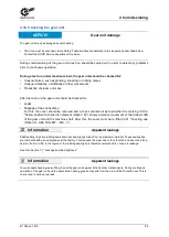
NOTICE!
Gear unit damage
The oil level must be checked prior to commissioning (Section 5.2.6 "Oil level").
Insufficient lubrication causes abnormal operation and damage to gear unit components.
If the gear unit has already been filled with an initial filling prior to delivery, the vents must be fitted after
installation.
Pos: 115 /Anleitungen/Getri ebe/4. Inbetriebnahme/Ölstand und Entl üftung_03 [B1050, B2050] @ 30\mod_1552989764844_388.docx @ 2513188 @ @ 1
The following table shows the usual fill levels of oil spaces on delivery:
Oil space
Oil filling
with
Without
Industrial gear units
X
Primary gear unit (Option: WG)
X
Auxiliary gear unit (Option: WX)
X
Connecting flange (Option: WX)
X
Turbo coupling
X
Oil tank (Option: OT)
X
Table 6: Oil spaces as delivered
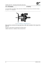
The position of the vents can be obtained from the specific dimension sheet for the order or from
Section 7.1 "Standard positions of the oil drain, vent and oil level". The sealing plug which is used for
transport must first be removed and the vent installed in the same position.
Information
Vent position
With the use of pressure vent (Option: DR) this must be unlocked for auxiliary (Option: WX) and first stage gear
units (Option: WG) prior to commissioning according to the operating and installation instructions B 1000.
The sealing plug which is used to close the vent hole for transport is marked with red paint.
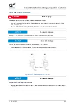
The connecting flange between the industrial gear unit and the auxiliary gear unit is always equipped
with a pressure venting device. This device, as well as the pressure venting device on the industrial
gear unit (only for ATEX-certified gear units) must be unlocked as shown unterhalb.
Summary of Contents for B 1050 Series
Page 1: ...B 1050 en Industrial gear units Operating and Assembly Instructions...
Page 5: ...Publisher B 1050 en 1819 5...
Page 87: ...7 Appendix B 1050 en 1819 87 Gear units SK 5207 SK 10507 M3 oil screw holes...
Page 89: ...7 Appendix B 1050 en 1819 89 Gear units SK 5207 SK 10507 M5 oil screw holes...
Page 93: ...7 Appendix B 1050 en 1819 93 Gear units SK 11207 SK 15507 M3 oil screw holes...
Page 95: ...7 Appendix B 1050 en 1819 95 Gear units SK 11207 SK 15507 M5 oil screw holes...
Page 112: ...6052902 1819...

