background image

SECTION 5

"

Connector Pin-Outs

5-2

6200 Hand-Held Computer

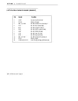
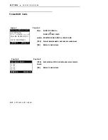
12-Pin Surface Contact Connector (standard)

Pin

Signal

Function

1
2
3
4
5
6
7
8
9
10
11
12

DTR

TPON
485-- & TPOP
TXD

CTS

DSR

CHARGE_DOCK

GND

RXD
485+ & TPIP

Ground (rightmost side)

RS-232 Data Terminal Ready

RS-232 Request To Send

RS-232 Transmitted Data

RS-232 Received Data

RS-232 Clear To Send

RS-232 Data Set Ready

RTS

TPIN

Ethernet Output
RS-485 I/O and Ethernet Output

Ethernet Input

RS-485 I/O and Ethernet Input

Dock Charge Voltage (leftmost side)

Summary of Contents for 6200

Page 1: ...6200 Hand Held Computer USER S GUIDE NPN 961 028 075 Revision A June 1995 ...

Page 2: ...assumes no responsibility or liability for any errors or inaccuracies that may appear in this document We welcome your comments concerning this publication Although every effort has been made to keep it free of errors some may occur When reporting a specific problem please describe it briefly and include the book title and part number as well as the paragraph or figure number and the page number S...

Page 3: ...sions from digital apparatus set out in the Radio Interference Regulations of the Canadian Department of Communications Le présent appareil numérique n émet pas de bruits radioélectriques dépassant les limites applicables aux appareils numériques de la classe B prescrites dans le Règlement sur le brouillage radioélectrique édicté par le ministère des Communications du Canada Telephone Installation...

Page 4: ...ique pendant un orage électrique S Ne jamais installer de prise téléphonique dans un endroit humide à moins que la prise ait été spécifiquement conçue pour être utilisée dans les endroits humides S Ne jamais toucher les fils de téléphone ou de l équipement terminal non isolés à moins que la ligne téléphonique n ait été débranchée de l interface réseau S User de prudence lors de l installation ou d...

Page 5: ...1 1 Section 4 1 1 Section 5 1 2 Section 6 1 2 Section 7 1 2 Hand Held Computer Description 1 2 Hand Held Computer Keyboard 1 6 Display 1 9 Battery 1 9 Memory 1 10 Main Memory 1 10 Flash ROM 1 11 CMOS RAM 1 11 PCMCIA Memory Cards 1 11 Diagnostic EEPROM 1 13 Reset Switch 1 13 Part Number Description for Your Hand Held Computer 1 13 Hand Held Computer Specifications 1 15 ...

Page 6: ...tery 2 9 Backup Battery Life 2 11 Dead Backup Battery 2 11 Downloading Programs into Your Hand Held Computer 2 12 Reset Switch 2 13 SECTION 3 Routine Care and Maintenance 3 1 Introduction 3 1 Main Battery Care 3 1 LOW BATTERY Indication 3 1 Charging the Main Battery 3 2 Charging the Battery in Your Hand Held Computer 3 2 Dead Backup Battery 3 2 Replacing the Backup Battery 3 3 Hand Strap Replaceme...

Page 7: ...Contact Connector standard 5 2 4 Pin RJ11 Connector optional 5 3 SECTION 6 Norand Utilities Program 6 1 Introduction 6 1 Program Conventions 6 1 Main Screens 6 3 Pop Up Menus 6 3 Drop Down Lists 6 3 Keyboard Standards 6 4 Boot Drive Utility 6 5 Screen Diagrams 6 6 Main Menu Entry Point 6 6 Language Selection Menu 6 6 Program Load Main Menu 6 7 Modem Parameters 6 9 Communication Status 6 10 Advance...

Page 8: ...ication 1 14 Figure 2 1 Installing and Ejecting PCMCIA Cards 2 3 Figure 2 2 Opening Main Battery Compartment 2 5 Figure 2 3 Main Battery Compartment 2 6 Figure 2 4 Installing Rechargeable Main Battery Pack 2 7 Figure 2 5 Top End Hand Strap Removal 2 9 Figure 2 6 Backup Battery Replacement 2 10 Figure 2 7 Reset Switch 2 13 Figure 3 1 Top End Hand Strap Removal 3 4 Figure 3 2 Backup Battery Replacem...

Page 9: ...ystem instructions Summary of Sections Section 1 Section 1 contains general information about the components of your 6200 Hand Held Computer This includes telling you how the user guide is orga nized a summary of the sections and the specifications for your hand held computer Section 2 Section 2 tells you how to prepare for using your 6200 Hand Held Comput er Section 3 Section 3 contains routine m...

Page 10: ...ng and setting parameters to support your application Section 7 Section 7 contains the Advanced Battery Management System information for running under DOS Hand Held Computer Description NORANDR hand held computers are used in the mobile systems market place to perform a wide variety of tasks Technology advances allow the design team at Norand to provide features and benefits to you in the 6200 ha...

Page 11: ...your 6200 hand held computer will work with the 4000 Series of printers communications controllers and communication docks The following descriptions will familiarize you with the name function and locations of the main hand held computer components Figure 1 1 and Figure 1 2 on pages 1 4 and 1 5 show you the location of these key com ponents ...

Page 12: ...00 Hand Held Computer 1 2 3 4 5 6 1 15 Pin Females D sub connector 2 RJ 11 jack Optional 3 Display Optional touch screen 4 Keyboard 5 Keyboard mounting screw 6 12 Pin surface contact connector Figure 1 1 6200 Hand Held Computer Front View ...

Page 13: ... 1 5 PCMCIA memory card door Backup battery inside Reset switch inside 2 1 3 4 5 6 1 2 3 4 5 6 7 7 Hand strap PCMCIA latch knob Main battery latch knob Main battery pack inside 8 8 15 Pin female D sub connector Figure 1 2 6200 Hand Held Computer Back View ...

Page 14: ... 1 7 and Figure 1 4 on page 1 8 detail the 30 and 56 key key boards 30 key fully numeric and special alphabetic characters using the shift key with touch screen 30 key full numeric and special alphabetic characters using the shift key without touch screen 56 key full numeric and alphabetic with touch screen 56 key full numeric and alphabetic without touch screen ...

Page 15: ...SECTION 1 General Information 6200 Hand Held Computer 1 7 1 2 3 1 2 3 Special function keys ON OFF key Numeric keys Figure 1 3 6200 Hand Held Computer With 30 Key Keyboard ...

Page 16: ...SECTION 1 General Information 1 8 6200 Hand Held Computer 1 2 3 4 1 2 3 4 Special function keys ON OFF key Alphabetic keys Numeric keys Figure 1 4 6200 Hand Held Computer With 56 Key Keyboard ...

Page 17: ...it in dark conditions Backlighting does however reduce battery life therefore turn off when done using The de fault setting for the backlighting feature shuts itself off after two minutes of use This time can be adjusted through your application settings The No rand Pen Key Programmer s Reference Guide NPN 977 028 014 contains details for adjusting contrast of the display and backlight setting Add...

Page 18: ...rechargeable battery design should give you approximately 500 cycles of use There are no guarantees on this number because it de pends greatly on how the battery pack is used and cared for The Routing Care and Maintenance section beginning on page 3 1 of this User s Guide provides detailed instructions for maintaining the rechargeable battery pack Your 6200 hand held computer will display an icon ...

Page 19: ...are available in a variety of memory sizes and types Check with your Norand Sales Representative or System Engineer for specific options Your 6200 hand held computer provides two PCMCIA slots Each slot ac cepts one PCMCIA Type 2 or Type 3 card These slots are used primarily for storage of data on a memory card much like a floppy disk drive on a PC You can use Type 2 or Type 3 cards in both Drive B...

Page 20: ...uter 1 2 3 4 PCMCIA door backup battery not shown in compartment Upper memory card drive B type 2 or type 3 cards Lower PCMCIA memory card drive A type 2 or type 3 cards Memory card eject buttons one on each side 3 4 1 2 Figure 1 5 PCMCIA Memory Card Slots ...

Page 21: ...lockup pressing the RESET switch will take you to the first screen of the application you were in It may be helpful to you to have either your company system programmers or the Norand System Engineer work with you to make sure all the ROM Utility Application parameters are set correctly The Reset Switch on your 6200 hand held computer is located so you can not accidentally hit it Section 2 shows y...

Page 22: ...chscreen 56 Key no touchscreen 56 Key with touchscreen Memory Options 0 1 2 3 2 Meg RAM 4 Meg RAM 8 Meg RAM future option 12 Meg RAM future option Dock Communications Options 517 Standard RS 485 and RS 232 only 518 Ethernet with RS 485 and RS 232 future option 6200 Hand Held Computer Part Number x x x x 1 5 Example Part Number 225 517 031 4 meg RAM 56 key with touch screen and 15 pin I O connector...

Page 23: ...30 ounces 850 5 g Humidity 5 to 90 noncondensing Static Protection 20 kV Power source Main battery AA size alkaline standard NiCd battery pack standard Nickel metal hydride pack optional Backup battery 9 volt alkaline standard Charging rate 0 to 60 _C 14 to 140 F Normal charge fully charge 2 5 hours Below 0_C Trickle charge Communication Interface RS 232 and RS 485 Ethernet optional Protocol Noran...

Page 24: ... DRAM 2 or 4 megabytes Card Options Two PCMCIA slots one type 2 and one type 3 or both can use type 2 cards Processor AM386XLV 3 3 volt 25 Mhz Display Type VGA compatible LCD standard touch screen optional Size 160 wide by 200 long pixel portrait orientation 160 wide by 300 long pixel available at a later date ...

Page 25: ...your 6200 hand held computer or any time that all power has been completely removed you are cold starting or cold booting your hand held computer The method you use to cold start your hand held computer depends on your application For example you may download transfer from the host computer to your hand held computer the application and data into your hand held computer Or you may use PCMCIA cards...

Page 26: ...py of the MS DOS 5 0 ver sion of COMMAND COM For complete details regarding creating a boot card refer to the instructions in the Pen Keyt Programmer s Reference Guide NPN 977 028 014 Put the boot card in Drive A or B before the main battery pack is installed see Figure 2 1 on page 2 3 for card slot identification If a startup card is not inserted before you attempt to start your hand held compute...

Page 27: ...einstall the compartment door and turn the latch knob 1 4 turn counterclockwise to lock it 1 2 3 Upper PCMCIA card drive B type 2 or type 3 cards Lower PCMCIA card drive A type 2 or type 3 cards Memory card eject buttons one on the other side not shown button on left is for drive B upper button on right is for drive A lower 3 1 2 Figure 2 1 Installing and Ejecting PCMCIA Cards ...

Page 28: ...rm a cold start Removing PCMCIA Cards The PCMCIA card compartment contains Ejection Buttons for remov ing the cards from the slots refer to Figure 2 1 on page 2 3 for loca tion These buttons have an arrow on them to identify the ejector for either the upper slot Drive B or the lower Drive A slot Press in on the ejector button to release and eject the card The button will eject the card far enough ...

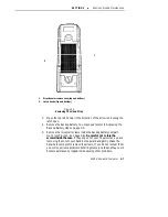
Page 29: ...gure 2 3 and Figure 2 4 on pages 2 5 2 6 and 2 7 1 4 turn counterclockwise Use a flat blade screwdriver or the edge of a coin to open the door Use a screwdriver or coin that fits the slot properly or in time it will wear away the corners of the latch knob 1 2 1 Main battery compartment 2 Latch knob turn counterclockwise to open clockwise to close Figure 2 2 Opening Main Battery Compartment ...

Page 30: ...SECTION 2 Hand Held Computer Operation 2 6 6200 Hand Held Computer Figure 2 3 Main Battery Compartment ...

Page 31: ...t The battery compartment contains a label showing the proper posi tioning of the pack with markings for placement of the positive and negative contacts The nickel cadmium NiCd or nickel metal hydride NiMh battery packs have three exposed electrical contacts The two round contacts are for the positive and negative terminals of the battery pack while the round surface contact is a switch plate that...

Page 32: ...er The following devices provide charging of the batteries while they are in the hand held computer 4960 MultiDock 4950 Single Dock 4810 4815 and 4820 Fixed mount Printer Many modems Backup Battery Your 6200 hand held computer comes with a 9 volt alkaline backup bat tery This battery provides protection of your data when the main bat tery is removed from the hand held computer or when the main bat...

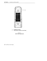
Page 33: ...n a flat surface Put it on a soft cloth or mat to prevent scratching it 2 Open the latch knob on the top end of the hand strap Refer to Figure 2 5 and Figure 2 6 on page 2 9 and 2 10 for hand strap and battery compartment part location Latch knob turn clockwise to open counterclockwise to close 1 1 Figure 2 5 Top End Hand Strap Removal ...

Page 34: ... 2 10 6200 Hand Held Computer Backup battery connector 1 1 Figure 2 6 Backup Battery Replacement 3 Snap the backup battery connector onto the battery 4 Slip the battery inside the holder and replace hand strap end cap 5 Close the latch knob ...

Page 35: ...bout 12 months Whenever your hand held computer alerts you that the backup is low replace the battery as soon as you can It protects your data Dead Backup Battery If both the main and backup batteries are dead you must reload your application program Usually your backup battery will fail only if the main battery is dead and the backup has maintained data in your hand held computer for approximatel...

Page 36: ... the downloading device The first screen you see will show you general information that being Norand Corporation program version and copyright data Press the YES key and con tinue This next screen will follow 1 BEGIN COMM SESSION 2 COMM NPCP NETWORK 3 UNIT ID xxxxxxx 9 ADVANCED UTILITIES NORAND UTILITIES LOAD PROGRAMS DATA The default setting BEGIN COMM SESSION will be highlighted If this is the s...

Page 37: ...er Support Specialist before you reset your hand held computer They might help you prevent resetting your hand held computer and losing your data The 6200 hand held computer design provides a starting point so you do not have to completely start over Figure 2 7 on page 2 13 shows the location of the Reset Switch Use a ballpoint pen when pushing the Reset Switch instead of a lead pencil Lead could ...

Page 38: ...SECTION 2 Hand Held Computer Operation 2 14 6200 Hand Held Computer ...

Page 39: ...nology works best when batteries rely on their own energy use that up and are then recharged The 6200 hand held computer protects itself from potential overcharges But leaving it out of charging sources ensures the longest battery life Maintenance procedures included in this section provides instructions on identifying Low Battery conditions replacing the hand strap and cleaning your hand held com...

Page 40: ...ging the Main Battery instructions that follows If it does not respond when inserted in the equipment that provides charging another problem could exist Refer to the Troubleshooting section for solutions Charging the Main Battery The battery pack will recharge in 3 4 hours either in or out of your hand held computer You must charge a new battery pack before using it To give you the most service fr...

Page 41: ...t in Section One page 1 15 indicates the type of backup battery to use Replacing the Backup Battery 1 Place your 6200 hand held computer on a flat surface Put it on a soft cloth or mat to prevent scratching it 2 Open the latch knob on the top end of the hand strap Refer to Figure 3 1 and Figure 3 2 on page 3 4 and 3 5 for hand strap part location Use a flat blade screwdriver or the edge of a coin ...

Page 42: ...SECTION 3 Routine Care and Maintenance 3 4 6200 Hand Held Computer Latch knob turn in direction of arrow to open Directional arrow on case 1 2 1 2 Figure 3 1 Top End Hand Strap Removal ...

Page 43: ...3 5 Backup battery connector 1 1 Figure 3 2 Backup Battery Replacement 3 Remove the battery from the connector and lift battery out 4 Snap the connector onto the new battery 5 Slip the new battery in the holder inside your hand held computer 6 Close the latch knob ...

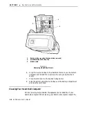
Page 44: ... of the arrow on the case with a coin or flat blade screwdriver Refer to Figure 3 3 on page 3 7 for help with these steps Use a flat blade screwdriver or the edge of a coin to open the door Use a screwdriver or coin that fits the slot properly or in time it will wear away the corners of the latch knob 2 Slide the hand strap off of the battery compartment This end stays with the hand strap You will...

Page 45: ...to refer to Replacing the Backup Battery steps on page 3 3 5 Remove the two small screws inside the backup battery compart ment see Figure 3 4 on page 3 8 Be careful not to lose the screws inside the case If they slip out of your fingers when you are removing them turn your hand held upward and gently shake the hand held computer to remove the screws If you do not recover them you will experience ...

Page 46: ...ap to the attachment holes on your hand held computer and reinstall the two screws Be sure you tighten them snugly 7 Close the latch knob on the top hand strap holder 8 Slide the bottom end of the hand strap over the battery compartment and close the latch knob Cleaning Your Hand Held Computer Periodic cleaning helps maintain the appearance and reliability of your hand held computer When cleaning ...

Page 47: ...nd held computer Never pour cleaners directly on the display or the case Instead put the cleanser on a soft cloth and gently wipe the case Case and Display Norand Corporation recommends cleaning the exterior of your 6200 hand held computer using a soft cloth dampened with MICRO CLEAN II cleans er made by Foresight International Inc 4887 F Street Omaha NE 68127 0205 Keyboard If necessary use a dry ...

Page 48: ...ld Computer Keyboard Retaining screw 1 2 1 2 Figure 3 5 Keyboard Removal Surface Connectors If surface connectors become dirty or tarnished clean them with a cotton swab dipped in alcohol It may also be necessary to lightly burnish them with a pencil eraser ...

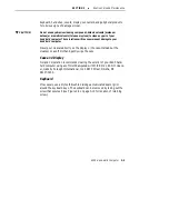
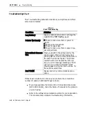
Page 49: ...iculties in routine operation printing or com munications there are a few things you may be able to do to correct the problem Refer to your applications software user manual for printing and telecommunication procedures Ensure that electrical and mechanical connections are secure and undamaged ...

Page 50: ...ter and try the printing again After a limited amount of printing has occurred remove the 6200 from the dock then connect again The printed result should occur despite the interrup tions An error message indicating a Print er Error 102 CHECK CONNECTION should appear during the interruptions Try this action several times Bad TCOM Review and retry communications proce dures If these basic solutions ...

Page 51: ... 800 633 6149 in Canada Diagnostic EEPROM Your 6200 hand held computer is equipped with a diagnostic EEPROM This EEPROM stores system service and diagnostic data It operates all the time but you are not normally aware of it You may be asked to perform tasks to help Norand Customer Support Specialist or the Cus tomer Response Hot Line Specialist diagnosis problems you are hav ing They will give you...

Page 52: ...SECTION 4 Troubleshooting 4 4 6200 Hand Held Computer ...

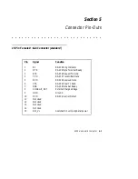
Page 53: ... 13 14 15 RI DTR RTS TXD RXD CTS DSR CHARGE_EXT GND DCD Not Used Not Used Not Used Not Used SW_V RS 232 Ring Indicator RS 232 Data Terminal Ready RS 232 Request To Send RS 232 Transmitted Data RS 232 Received Data RS 232 Clear To Send RS 232 Data Set Ready External Charge Voltage Ground RS 232 Carrier Detect Switched 5 0 volt peripheral power ...

Page 54: ... TPON 485 TPOP TXD CTS DSR CHARGE_DOCK GND RXD 485 TPIP Ground rightmost side RS 232 Data Terminal Ready RS 232 Request To Send RS 232 Transmitted Data RS 232 Received Data RS 232 Clear To Send RS 232 Data Set Ready RTS TPIN Ethernet Output RS 485 I O and Ethernet Output Ethernet Input RS 485 I O and Ethernet Input Dock Charge Voltage leftmost side ...

Page 55: ...SECTION 5 Connector Pin Outs 6200 Hand Held Computer 5 3 4 Pin RJ11 Connector optional Pin Signal Function 1 2 3 4 TIP RING Modem TIP Modem RING ...

Page 56: ...SECTION 5 Connector Pin Outs 5 4 6200 Hand Held Computer ...

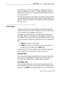
Page 57: ...countries throughout the world If your application does not require languages other than English your 6200 hand held computer will automatically bypass this option Program Conventions The display screen consists of a screen title main screen pop up menus drop down lists descriptive text and keyboard key definitions Depending on your application needs you may not see some of these elements An ex am...

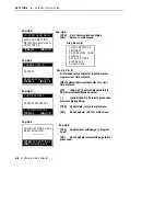
Page 58: ...NTERNAL 14 4K 6 OTHER MODEM 7 NO MODEM Entry Point NORAND UTILITIES PSROMOC Vx xx The keys you are instructed to use will show in the display in square brack ets e g YES in both the screen diagrams and descriptive text Fixed fields are represented by all uppercase letters on screen diagrams and in text MODEM PARAMETERS Variable fields are represented by at least one lower case character using x an...

Page 59: ...contain fields defining action keys that are enabled This information will be displayed in reverse video Keys used to move within the screen e g arrow keys are not shown When the following keys are present they will be displayed in the indicated posi tions NO QUIT last line right justified YES literal last line left justified or second to the last line if too long to fit on the same line with NO Q...

Page 60: ...y that the next logical step in a process will be executed YES UPDATE writes the new value of one or more fields on the current screen to memory In addi tion the updated screen is cleared and control moves to the location indi cated YES inputs the value entered in a user input field NO QUIT cancels an operation returning control to the prior logical step thereby skipping the current operation DEL ...

Page 61: ...to change the default Do not have a PCMCIA card in either Drive A or B You will not be able to change drives if you have a card in either of the slots After you RESET your 6200 hand held computer press the F4 key The following popup menu will display ROM DOS 5 Start From 1 Memory Card 1 A 2 Memory Card 2 B 3 RAM Drive C 4 ROM Drive D Make your selection ...

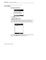
Page 62: ...ge Selection Menu Your application checks files to determine available language options Eng lish will always be the first option followed by up to nine additional choices If no resource files on language exist this menu will not display NORAND UTILITIES LANGUAGE SELECTION 1 ENGLISH 2 3 4 5 6 7 8 9 0 NO QUIT Select the appropriate language by pressing the number associated with your choice or press...

Page 63: ...D UTILITIES D Menu options 4 5 visible only if comm set MODEM D comm set value from Drop Down B Default NPCP NETWORK D mdm type prot bps f value from Modem Parameters Drop Down A1 A4 D Unit ID defaults to serial ID field unless modified by previously loaded application 1 If comm set HAND HELD then to Pop Up A Else go to Communication Status 2 Drop Down B 3 Pop Up C 4 Go to Modem Parameters Pop Up ...

Page 64: ...ZZZZZZZZZ DIALING PAUSE YES OK NO QUIT Pop Up D COMM SETTINGS HAVE BEEN CHANGED YES SAVE SETTINGS NO DO NOT SAVE Pop Up E Pop Up A First alphanumeric character input character clears current field contents DEL deletes right most character of current field contents F4 Pop Up C Restore field value to EE PROM serial identification number period Pop Up D inserts pause char acter into dialing string YE...

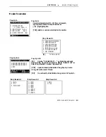
Page 65: ...ZZZZZZZZZZZZZZZ XZZZZZZZZZZZZZZZ XZZZ F2 TEST STRING YES OK NO QUIT Pop Up A16 Pop Up A F2 Display PLEASE WAIT on blank line and send modem string Upon modem response display RESULT 99 on blank line where 99 modem response code YES Update modem initialization string Pop Up A note string will not be saved if blank NO Do not modify initialization string return to Pop Up A Pop Up A16 1 MODEM TYPE x m...

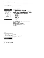
Page 66: ...G x filename x LOADING x filename x SIGNING OFF Filename field displays name of the file being processed when SENDING or LOADING Byte count applicable to current file only Error count is the total number of protocol errors in the current comm session NO Pop Up A NORAND UTILITIES COMMUNICATIONS NO STOP COMM ARE YOU SURE YOU WANT TO STOP COMMUNICATIONS NOW YES STOP NO RESUME Pop Up A COMM SETTINGS x...

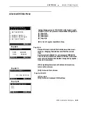
Page 67: ...re not modified unless new values are en tered i e changing the date does not affect the current time Date format is MM DD YY year is assumed 1980 2079 Time format is HH MM SS based on 24 hour clock Maxi mum entry is 23 59 59 Punctuation is supplied by applica tion and is not entered YES Update system clock with date and time entries return to Main Screen NO Return to Main Screen Pop Up A Pop Up C...

Page 68: ...NTINUE YES OK NO QUIT Pop Up 2 YES Set boot drive CMOS variable and return to main screen NO Return to main screen Pop Up E Pop Up 2 title FORMAT DRIVE c or FORMAT RAM CARD media EXISTING RAM DRIVE or RAM CARD YES Format selected media and return to main screen NO Return to main screen Pop Up E SET BOOT DRIVE YES OK NO QUIT 1 A 2 B 3 C 4 D ...

Page 69: ... can prevent a pop up from occurring or clear one that is already displayed Certain applications may put the screen information into a mode that BAT WARN does not support in which case no pop up will occur A warning BEEP will signal that a pop up did not appear because the videocontroller was in an unsupported mode Power conditions which will cause a pop up window to appear are Backup Battery Low ...

Page 70: ...ery Critical at each re sume and displays the pop up if appropriate In addition BATWARN will also display low battery warnings at resume time 10 20 30 minute as well as when the actual event occurs Battery Full is only displayed when the unit is removed from the charger and the battery full flag is set by the APM ...

Page 71: ... Management System 6200 Hand Held Computer 7 3 Battery Management Icons Full Critical low 10 Minutes Remaining 20 Minutes Remaining 30 Minutes Remaining Main Battery Backup Battery In Charger Low Figure 7 1 Graphic Mode Icons ...

Page 72: ...Advanced Power Management System 7 4 6200 Hand Held Computer Full Critical low 10 Minutes Remaining 20 Minutes Remaining 30 Minutes Remaining Main Battery Backup Battery In Charger Low Figure 7 2 Text Mode Icons ...

Page 73: ...ns 7 3 Boot Drive Statement 2 2 See also boot drive utility Boot Drive Utility 6 5 See also boot drive statement C Charging Main Battery 2 8 3 2 in hand held computer 3 2 Cleaning case 3 9 contact surfaces 3 9 display 3 9 hand held computer 3 9 keyboard 3 9 Cleaning Contact Surfaces 3 10 Cleaning Keyboard 3 9 Compatibility 1 2 4000 series products 1 2 Connectors 5 1 12 pin surface contact field 5 ...

Page 74: ...stalling 2 2 removing 2 4 PCMCIA Memory Cards 1 10 types type 1 1 11 type 2 1 11 Power Conditions 7 1 pop up messages 7 1 Product Feature Descriptions 1 3 R Removing Memory Cards 2 4 Removing PCMCIA Memory Cards 2 4 Repair Service 4 3 Replaceable Alkaline Backup 1 10 Replacing Hand Strap 3 6 Reset Switch 1 13 Reset Switch Location 2 13 S Specifications 1 15 T Text Mode Icons 7 3 Touch Screen Displ...

Reviews: