background image


1.  Introduction 

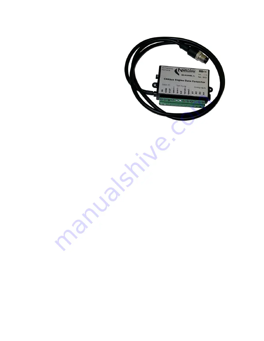
The RS11 Engine Data Converter converts tachometer signals and analog gauge voltages from virtually any engine into 
CANbus digital messages compatible with J-1939 and NMEA 2000 protocols.  It is configurable for either single or dual en-
gine installations.  The user must configure the RS11 for the desired data and calibration parameters such as pulses/rev, ana-
log scale factors, etc.  Configuration is performed via a Serial (RS-232) PC interface which also serves as an output data 
monitor, if desired.  Output messages are applied to the CANbus, which can then be viewed by any compatible display.  
Power for the RS11 is supplied by the CANbus. 


2.  General 

The RS11 is designed for versatile interfacing to almost any type of analog engine sensor or gauge commonly used on marine 
or automotive engines.  It has two RPM (tach) inputs, four analog (gauge) inputs and supports both 12 and 24 volt systems.  
The analog inputs can be assigned all to one engine or be split between two engines.  Multiple RS11's can be installed on the 
same CANbus.


The RS11 should generally be used in conjunction with existing analog gauges rather than as a replacement for them.  This is 
because most sensors are “energized” by the existing engine gauges.  The RS11 is designed to “piggyback” onto these gauges 
rather than replace them.  The RS11 inputs are ‘passive’ in that they read sensor/gauge voltages but do not power them.    
 
The RS11 supports messages most commonly used by marine and industrial CANbus engines.  The user must perform an 
initial configuration of the unit to suit the particular engine(s).  This consists of selecting the specific information to be sent 
and entering proper calibration factors.  Configuration is done through a PC Serial interface and Setup Utility (see Appendix 
D) provided with the unit. 
 
Typical installations for a single and dual engine are shown in Figure 1.  For the single engine case, one RPM input is not 
used, and all analog inputs are available for that engine.  In the dual engine case, the analog inputs must be divided between 
the two engines.  This usually means each engine only gets two analog inputs.  To get four analog inputs to each of two en-
gines, you can use two RS11's, one for Port Instance and the other for Starboard Instance. 


Model RS11 v3.0 

CANbus Engine Data Converter 

NoLand Engineering, Inc. 

 
TABLE of CONTENTS 
 

1.  Introduction    
2.  General Description 
3.  Installation 
4.  Operation 
5.  Technical Specifications 
6.  Warranty 
 
Appendix A - CANbus Messages 
Appendix B - Programming Instructions 
Appendix C - Gauge/sensor calibration examples 
Appendix D - RS11 Setup Utility 

Summary of Contents for RS11 v3.0

Page 1: ...are energized by the existing engine gauges The RS11 is designed to piggyback onto these gauges rather than replace them The RS11 inputs are passive in that they read sensor gauge voltages but do not...

Page 2: ...m1 Engine tachometer Port or Single input ref 2 5V reference signal used for some tach connections rpm2 rpm2 Engine tachometer Stbd input A1 A4 Analog inputs selectable ranges 5V 15V 30V CANbus cable...

Page 3: ...rnal shutdown or reset of the unit This is par ticularly useful if the RS11 must be shut down when the engine is stopped A switch or relay closure can serve as the shut down interface Serial PC Interf...

Page 4: ...put is measuring the voltage of a 12 volt marine battery the full scale voltage should be set to 15V For measuring a 24 volt battery the full scale voltage should be set to 30V All jumpers are factory...

Page 5: ...ase is probably between 12 and 36 so pick a number send it to the RS11 and test Configuration Setup The RS11 must be properly configured before it will send any useful data The following preparation s...

Page 6: ...f the RPM seems wrong it may be due to the wrong ppr value in the RS11 See Appendix B for instructions on changing the RPM ppr value s The sentences beginning with PNOLA x x x x x x x x x x x x A1 A2...

Page 7: ...cerning this product It is the customer s responsibility to return the product safely to NoLand Engineering Unless other arrangements are made the customer must properly pack ship and insure the unit...

Page 8: ...ge frame The PGN specifically identifies the contents of each message The table below lists the PGN s supported by the RS11 PGN s below 65535 may be used by all 3 protocols whereas those above belong...

Page 9: ...items in the above list If however two engines are being supported with one RS11 you would have to divide up the available Analog Inputs A1 A4 between your two engines Transmission Parameters This si...

Page 10: ...disconnect reconnect Help Query configuration n a Shows current device configuration I or i Set Instance ID Port Stbd 0 9 Port 0 2 4 6 8 Stbd 1 3 5 7 9 P or p Port pulses per revolution ppr 000 250 Le...

Page 11: ...2 and 3 respectively Note that both lower and uppercase commands are valid To confirm the change type another and look for the Instance ID s at the end of the first line as shown below It will remain...

Page 12: ...lt trim Instance 0 R3 or r3 A3 Stbd Turbo Boost Instance 1 R4 or r4 A4 Port Tilt trim Instance 1 Sending any of the above commands with a rather than a sign will remove the assignment for input so tha...

Page 13: ...stance 0 Stbd Trans Temperature Instance 1 Table B4 Transmission Parameters Message data field assignments To remove any of the Table B4 assignments send the command M or m where is the Analog Input 1...

Page 14: ...eter may be needed to determine these points but the RS11 can be used as a voltmeter as described later Our first point on the curve is usually easy to obtain For the case of Oil Pressure we know the...

Page 15: ...ich can also serve as an output data monitor if desired The RS11 must be properly configured before it will send any meaningful data The following preparation should be done before configuring the RS1...

Reviews: