1
RCS770
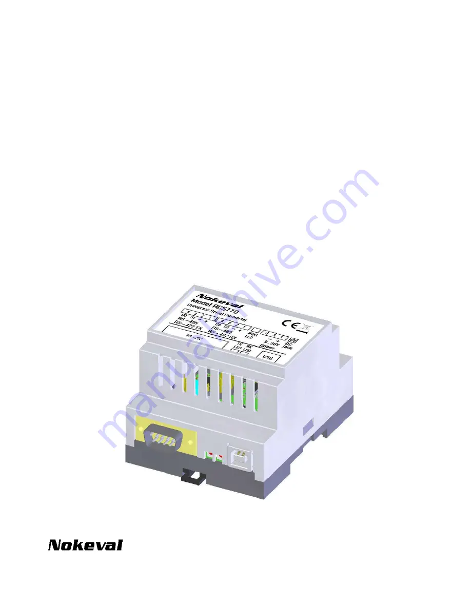
USB / RS-485 / RS-232 converter
User Manual
23.5.2006
V1.0
Page 1: ...1 RCS770 USB RS 485 RS 232 converter User Manual 23 5 2006 V1 0...
Page 2: ...pass various serial protocols including Nokeval SCL Modbus ASCII Modbus RTU and HART The RS 485 direction is changed automatically no handshake lines are required RS 485 bus is attached via screw ter...
Page 3: ...10 J7 An external power supply can be connected here J6 RS 232 port J2 USB port Indicators LED Purpose D1 This converter is powered up USB drivers are working D2 This converter is receiving data from...
Page 4: ...ected to a computer See page 11 on drivers RS 485 buses J3 are J4 equal Any or both of them may be used See page 12 No external power supply is required but J8 can be used to power up the RS 485 devic...
Page 5: ...J11 and J9 are not used Connections USB is connected to a computer See page 11 on drivers J3 and J4 are the RS 422 bus This device transmits at J3 and receives at J4 No external power supply is requir...
Page 6: ...ing to the picture J1 J5 J11 and J14 have no effect Connections USB is connected to a computer See page 11 on drivers How to use the RS 232 bus see page 15 No external power supply is needed 6 4 3 2 1...
Page 7: ...to control the baud rate and bit format Connections RS 485 buses J3 and J4 are equal Any or both of them may be used See page 12 RS 232 bus is explained on page 15 This converter must be powered exter...
Page 8: ...d rate and bit format see picture below Connectors J3 is RS 422 Tx and J4 is Rx See page 14 RS 232 is explained on page 15 An external power supply must be connected in J7 or J8 see page 10 8 4 3 2 1...
Page 9: ...baud rate and bit format Connectors J3 and J4 are the RS 485 buses Data on either bus is repeated onto the other This converter must be powered up from an external supply brought to connector J7 or J...
Page 10: ...ot generate this supply voltage and it must be brought to connector J8 or J7 If you use J7 read the section Jumper J14 below RCS770 itself does not care which way the bus devices are powered This powe...
Page 11: ...okeval Software CD before plugging in the device The device can then be plugged in and all is done When the drivers are successfully installed the power indicator on RCS770 should light up Virtual ser...
Page 12: ...ed A and B have been used with two meanings Nokeval has decided to use the names defined by Modbus standard D1 and D0 The table below lists common names for the lines D1 D0 B A A B Cable The D1 and D0...
Page 13: ...5 transmitters waits another 1 2 bytes and then starts transmitting the data on the bus When the last bit has been transmitted the RS 485 transmitter is disabled to allow receiving data Because the di...
Page 14: ...Tx Tx Rx Rx Cable The cable should consist of twisted pairs so that TXD1 and TXD0 form one pair and RXD1 and RXD0 another The minimum recommended diameter for the cable is 0 5 mm 24 AWG In a noisy en...
Page 15: ...and 5 5 Pin Name Purpose Direction 1 DCD Carrier detected In 2 RxD Data receive In 3 TxD Data transmit Out 4 DTR RCS770 is ready Out 5 Gnd Ground 6 DSR Other device is ready In 7 RTS RCS770 requests t...
Page 16: ...the application is using a wrong COM port probably This test is not applicable if USB is not used Step 3 Reception If Tx is blinking but Rx is not your RS 485 device is not responding Check that it i...