32
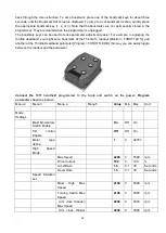
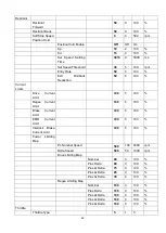
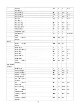
Tests
Test Enable
0
0
1
Test Throttle
0
-1
1
Motor Poles
4
2
8
Max Test Speed
1000
500 3000
rpm
Max Test Current
80
20
100
%
SlipGain
3.85
0
200
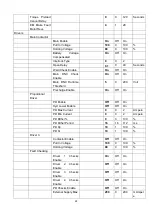
Field Weakening
Control
FW Base Speed
1550
200 6000
rpm
Field Weakening
30
0
100
%
Weakening Rate
40
0
100
%
Min Field Current
0
0
800
Ampere
Motor Type
0
0
205
Reset
Controller
0
0
1
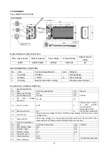
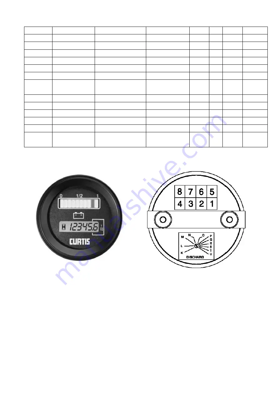
3.7 BATTERY INDICATOR
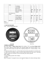
Type: CURTIS 803RB2448BCJ3010
Front View Rear View
TERMINAL ASSIGNMENT
Pin 7 or 8
= B.
Single voltage models
: Pin 8 to b; Pin 7, open.
Dual voltage models
:
When vehicle voltage is the higher voltage of the 2 operating voltages, Pin 8 connects to b; Pin 7,
open. When vehicle voltage is the lower of the 2 operating voltages, Pin 7 connects to b, Pin 8,
open.
The discharge indicator uses Pin 7 or 8 for its battery state-of-charge measurements. Connection are to
be made as close as possible to battery to prevent voltage drops that will cause errors in discharge
indicator readings. The connection is not to be switched by the vehicle’s keyswitch.
Pin 5
= Battery –
Connect to battery ground as close to battery
as possible.
Pin 2
= Keyswitch. The keyswitch turns on and off the LED display of the battery discharge indicator.

