19
Front and rear panels
needed, however only the backplane connector in the right side slot connects to the
module’s rear panel electrical connector.
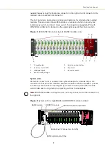
The front panel also incorporates controls and indicators for managing the inserted
modules. These include: status LED indicators, an emission button, a security and
interlock key switch, and an AC mains switch. To connect a management PC (with
CONTROL), a USB port is located on the upper right panel of the control section.
Figure 3
ACOUSTIK front panel layout - BASIK modules only
System slots
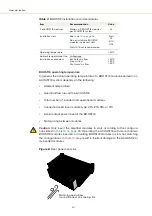
At the back of each slot, mounted on the system backplane, a female 30 pin C/3
connector connects to each module’s electrical connector. When a module is pushed
into the slot, the connectors are aligned by a hole in the rear panel of the module
which slides over an alignment pin projecting out from the backplane.
Note:
BOOSTIK modules occupy two slots, but only connect to the C/3 connector of
the right
slot.
Figure 4
System with a single BASIK and BOOSTIK module installed
1
16 module slots
5
Emission control button
2
Summary status LEDs
6
Key switch
3
USB type B port
7
AC mains switch
4
Rack mounting flanges
1
3
4
5
6
2
7
4
BASIK module
BOOSTIK module
BASIK optical output fiber
BOOSTIK optical output fiber
Backplane C/3 connectors (total 16)
Summary of Contents for Koheras ACOUSTIK
Page 1: ...Item 800 633 01 Koheras ACOUSTIK PRODUCT GUIDE Multi Channel Modular Laser System...
Page 10: ...10...
Page 14: ...14...
Page 16: ...16...
Page 26: ...System labels 26...
Page 28: ...28...
Page 34: ...Operating and storage environment 34...
Page 42: ...42...
Page 78: ...Module overview 78...
Page 80: ...80...
Page 82: ...82 Figure 44 Mechanical dimensions 483 00 45 00 302 50 4 50 125 00 2...
Page 92: ...Installing CONTROL 92...
Page 95: ......
Page 96: ...1 Koheras ACOUSTIK Product Guide Revision 1 0 09 2021 W 10456...


