Control panel
50
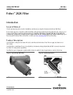
Figure 35
Channel controls - general operation
Crystal
Select either the VIS/NIR or NIR/IR AOTF crystal. The
is displayed for
the crystal selected.
Note:
The
Crystal
selection (i.e. the AOTF selection) is locked when a single ERD
is equipped with the system RF power ON (see
).
For dual External RF Driver systems, the crystal selection is available (when two
RF driver signals are present) and channels can be activated on both AOTFs.
Note:
To change crystals on a single ERD system, remove the channels from the
current
Crystal
and turn OFF the RF power from the ERD.
Channel buttons and text input fields
8 channel buttons and their settings are available for each crystal. You can set
the power level and wavelength of each channel using the input text fields or
clicking the set button. Clicking the channel button ON (green) enables the
channel and it appears as a numbered symbol in the
. When the
channel button is ON and laser emission is enabled, an output beam emits from
the crystal at the set channel parameters.
Set button
Instead of the band view, you can display sliders for each channel. Click the set
button to display the sliders for the channel setting. Click-hold and adjust the
sliders with your mouse to set the power and center wavelength of the channel.
To close the slider view, click the X in the upper right corner.
Channel buttons and
Select an AOTF crystal
Band view with
Click the channel # toggle
to turn it ON, it’s icon
appears in the band view
ettings
channel 1 displayed
s
Operating mode
drop down selection
Summary of Contents for A203-000-001
Page 1: ...SuperK SELECT PRODUCT GUIDE Multi Channel Tunable Filter...
Page 8: ...8...
Page 10: ...10...
Page 14: ...14...
Page 30: ...Status LEDs 30...
Page 56: ...Control panel 56...
Page 59: ...59 Figure 44 Mechanical dimensions External RF Driver...
Page 60: ...60...
Page 62: ...Support Contact Details 62 2...
Page 68: ...Installing CONTROL 68...
Page 77: ...SuperK SELECT Product Description Revision 1 00 10 2020 W 10456...