nitedevil CAM630 Manual Download Page 1

             www.nitedevil.com

Doc XCAM630

                                    NiteDevil Hi-Res 600TVL Colour Dome Camera

Email:

[email protected]

                                                                                              Last Revised: 15/06/2012
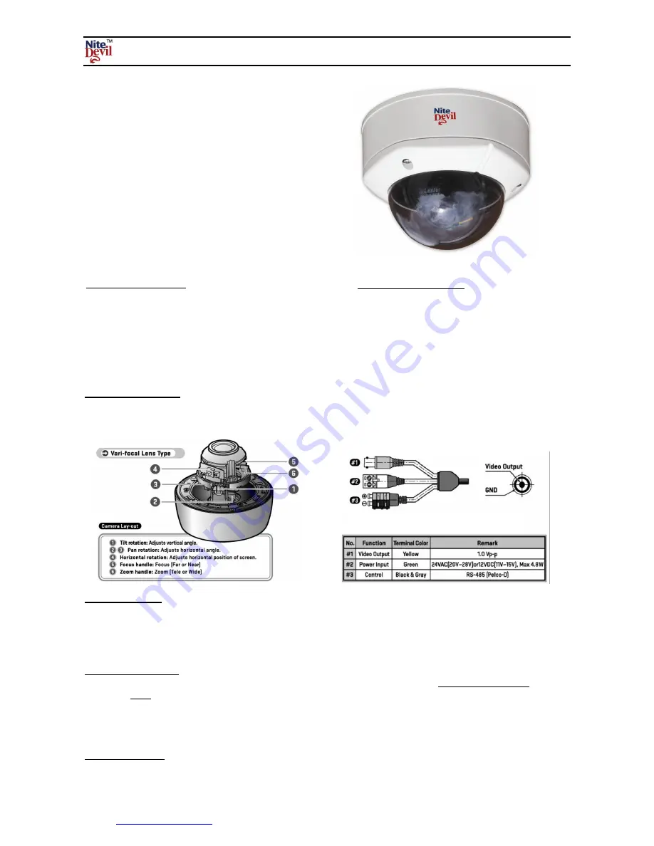
Mounting the Camera

The camera is for mounting on a wall, ceiling or outdoor facia board. An optional wall bracket is also available. Note
that this camera has a 3D gimble allowing wall mounting as well as ceiling mounting. Note that fitting the screws into
a ceiling will require support for the screws.

Connecting Video

The dome camera comes with a fly lead for video out.  To reduce installation time the video out lead is terminated into
a  female BNC connector.  This allows the installer to effortlessly connect the camera to control equipment via a BNC
lead.  A special setup joystick controller is located on the side of the PCB board and this allows access to the OSD
menu. A short RCA lead and connector is supplied to connect an optional test video monitor.

Powering the Camera

The dome requires either a 12V DC regulated or 24vAC power supply. Connections

are polarity sensitive

 therefore

the power

must

  be  connected  the  right  way  round.  The  camera  is  provided  with  a  fly  lead  with  a  green  and  black

terminal connector for power. This camera draws a maximum of 300mA at 12v DC. Ensure that a regulated power
supply is used if using 12vDC and allow adequate headroom i.e only use a power supply with a minimum rating of
500mA.

Connecting RS845

The RS485 for controlling the menu has a black and grey terminal connector. You can use a CAT5 pair without
baluns.
The terminal connector has a press button to secure cable connections, which must be connected to a keyboard or DVR
using the correct polarity.

CAM630 WDR NiteDevil Dome

The CAM630

NiteDevil

 Dome Camera produces high

quality images and works in very low light conditions
0.0001 Lux. The dome has many features including a
3D axis mounting inner bracket for wall mounting, 600
TVL, SONY SuperHad CCD, 2.8mm ~ 10.5mm
varifocal lens and an OSD facility for balancing light
levels at night (Shield function), motion detection,
privacy masking and camera setup options. This
camera has remote menu control using the RS485
interface and gives extraordinary results day and night.

Electronic Features

 1/3” SONY SUPER HAD 600 TVL CCD
 Low illumination down to 0.0001 Lux
 Menu for motion detection & camera setup
 Dual power 12vDC or 24vAC polarity sensitive
 Accidental surge & electronic shock protected.
 RS485 control for menu control

Mechanical Features

 Vandalproof, weatherproof & tamperproof
 Shield function for night time viewing
 3 Axis 3D built-in bracket
 Vari-focal 2.8 ~ 10.5 mm auto DC iris lens
 Aluminium housing with polycarbonate

 smoked cover

Summary of Contents for CAM630

Page 1: ...Ensure that a regulated power supply is used if using 12vDC and allow adequate headroom i e only use a power supply with a minimum rating of 500mA Connecting RS845 The RS485 for controlling the menu h...

Page 2: ...1 ATW2 W BALANCE PUSH COLOUR TEMP INDOOR OUTDOOR RED 100 100 MANUAL BLUE 100 100 NOISE REDUCE ON LEVEL 0 63 MOTION ON OFF ZOOM X1 00 x 6 13 DZOOM PAN 100 100 DIGITAL ZOOM DZOOM TILT 100 100 FLIP OFF V...

Page 3: ...the SET button down The above menu shows the default settings The Initial option it the submenu only defaults that menu If you wish to default all settings you must select NITEDEVIL RESET in EXTRAS me...

Page 4: ...d letter and select the letter by pressing the MENU button 1 3 Repeat this to enter multiple letters 1 4 You can enter up to 15 letters 2 LENS This option set to DC LENS 3 NITEDEVIL This options allow...

Page 5: ...NITIAL SET This allows defaulting the settings of this menu Select INITIAL SET using the UP or DOWN button and then press the MENU button 4 DAY or NIGHT This option sets DAY colour only NIGHT b w only...

Page 6: ...VEL BLC compensation level Select from LOW MIDDLE and HIGH using the LEFT or RIGHT button 5 3 1 AREA SETTING Select AREA setting using the UP or DOWN button and then press MENU button to enter mode Th...

Page 7: ...TEMP Select Indoor or Outdoor Select between Indoor and Outdoor using the LEFT or RIGHT button INDOOR 3200 K OUTDOOR 5100 K 6 4 2 RED Select RED using the UP or DOWN button You can adjust the RED colo...

Page 8: ...n 0 100 using the LEFT or RIGHT button 8 6 CR GAIN Select red gain between 100 100 using the LEFT or RIGHT button 8 7 CB GAIN Select blue gain between 100 100 using the LEFT or RIGHT button 9 EXTRAS S...

Page 9: ...ing LEFT or RIGHT button 9 2 4 MOVE X Move Horizontal Position You can move the horizontal position of the zone between 8 92 by using LEFT or RIGHT button 9 2 5 MOVE Y Move Vertical Position You can m...

Page 10: ...FT or RIGHT button 9 3 7 MOVE Y Move Vertical Position You can move the vertical position of the mask between 2 98 by using LEFT or RIGHT button 9 4 MENU The Language is ENGLISH only 9 5 ANTI SHAKE Th...

Page 11: ...onnections are correctly connected on the keypad or DVR On the Alien DVR the T refers to the and the T refers to the connections The control works only on the PELCO D setting and this must be set in t...

Page 12: ...Digital Zoom X 1 00 x 6 13 Day or Night AUTO DAY NIGHT NITE TURBO ON OFF Motion ON OFF 4 programmable Zones Privacy ON OFF 8 programmable Zones RS485 menu control PELCO D protocol baud rate and ID adj...

Reviews: