ENGLISH
USER MANUAL
6
146 2494 000(2)2007-02 A
SR 1100S B
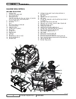
MACHINE DESCRIPTION
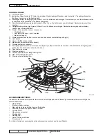
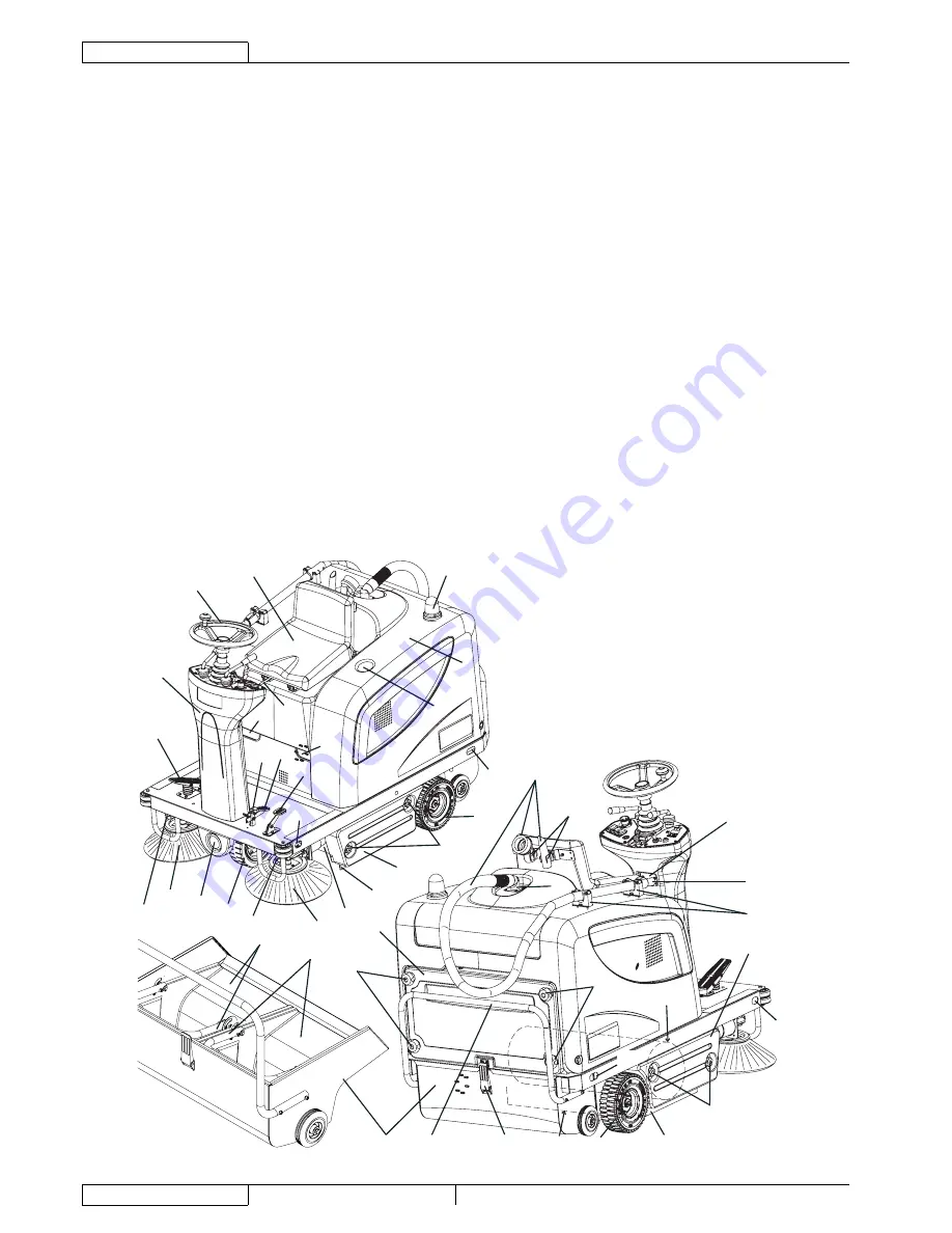
MACHINE STRUCTURE
Steering wheel
Forward/reverse gear pedal
Service brake pedal
Parking brake lever
Press the brake pedal (3), then use the lever (4) to switch
from the service brake to the parking brake.
Front skirt lifting pedal
Can holder
Hood
Rear driving wheels on fi xed axle
Front steering wheel
Right side broom
Left side broom (optional)
Main broom
Left side skirt
Right side skirt
Front skirt
Rear skirt
Hopper (empty it when it is full)
Hopper fastening hook
Hopper handle
1.
2.
3.
4.
5.
6.
7.
8.
9.
10.
11.
12.
13.
14.
15.
16.
17.
18.
19.
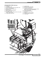
Left door (to be opened for performing maintenance
procedures only)
Door knobs
Right door (for main broom removal)
Door knobs
Flashing light (always on when the ignition key is turned to
"I") (optional)
Driver's seat with safety microswitch
Additional hole for manual vacuum system kit (optional)
Adjustable steering column
Working light (optional)
Right side broom height adjusting knob
Left side broom height adjusting knob (optional)
Seat longitudinal position adjusting lever
Vacuum fi lter compartment cover
Cover knobs
Manual vacuum system (optional)
Manual vacuum system fasteners
Internal containers with handle for dumping (optional)
Serial number plate/technical data/conformity certifi cation
Hood opening handles
Machine lifting anchors
20.
21.
22.
23.
24.
25.
26.
27.
28.
29.
30.
31.
32.
33.
34.
35.
36.
37.
38.
39.
36
36
17
18
16
12
19
33
32
33
22
23
14
35
34
37
26
35
34
6
7
24
25
1
31
27
2
3
4
5
8
21
20
13
15
11
30
9
28
10
29
38
38
39
39
39
39
8
S311408
Summary of Contents for SR 1100S B LSB*
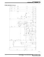
Page 61: ...USER MANUAL ENGLISH SR 1100S B 146 2494 000 2 2007 02 A 11 WIRING DIAGRAM Continues S311411 ...
Page 99: ......
Page 100: ......

