background image

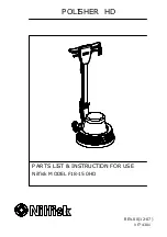
      POLISHER  HD

REV.00(12-07)

VF74301

PARTS LIST & INSTRUCTION FOR USE

Nilfisk MODEL F18-150HD

Summary of Contents for F18-150HD

Page 1: ...POLISHER HD REV 00 12 07 VF74301 PARTS LIST INSTRUCTION FOR USE Nilfisk MODEL F18 150HD...

Page 2: ...achine Operation Chinese 12 13 Wiring Diagram 14 2 WHEN ORDERING PARTS Use the 7 8 or 9 digit part numbers from the part number columns in this parts list Specify the model and serial number of the ma...

Page 3: ...have read and understand operators manual In flammable or explosive areas With a damaged cord or plug If not in proper operating condition In outdoor areas In standing water With the use of extension...

Page 4: ...When the machine is in operation both hands should be placed on the switch housing upper handle 9 During operation to make the machine go right gently raise the handle To make the machine go left gent...

Page 5: ...niformly Be sure to grind slowly and evenly with enough water You must completely remove the powder from the last process before beginning next process Immediately clean the floor with the vacuum clea...

Page 6: ...PARTS LIST HANDLE GROUP FOR F18 150HD...

Page 7: ...ET CORD 1 21 VF74105 HANDLE TUBE ALU 1 22 VA13474 SCREW M5 X 16 PH M5 X 16 1 23 VF40994 READ MANUAL LABEL 1 24 VF72721 POWER CORD 1 25 VV67105 CONNECTOR 1 26 VF72722 CORD 1 27 VF46708 LEVER SOLUTION 1...

Page 8: ...2 M5 X 12 2 65 VF13638 SCREW HEX HEAD M5 43 M5 43 1 66 VF14112 SCREW PAN HEAD M5 38 M5 38 1 67 VF47034 SPACER CLAMP PLATE 2 68 VV20275 WASHER PLAIN 3 16 3 16 2 69 VF72104 BRACKET TANK 1 70 VV13635 SCR...

Page 9: ...BASE GROUP FOR F18 150HD PARTS LIST...

Page 10: ...RON BAR 3 13 VA13474 SCREW M5 X16 PH M5 16 5 14 VF13474A WASHER PLAIN 5 4 15 AS22002 SCREW M5 X 16 HEX SOCKET M5 X 16 5 16 GT13023 SCREW PAN HEAD M5 53 M5 53 4 17 VF13524 WASHER PLAIN 8 7 18 VF13519 W...

Page 11: ...SCREW FLAT HEAD M4 12 M4 12 2 37 VF32109 1 38 VF72124 HOLDER BIG CAPACITOR 1 39 VF999849 1 40 YLQ17507 BOLT WITH WASHER KIT 4 41 VF999791N MOTOR WITH GEAR BOX ASSY 1 42 VF74101 COVER MOTOR 1 43 VF721...

Page 12: ...1 l l l l l l l l 2 l 3 l l l l l l l 4 l 5 l l 1 2 3 1 2 3 4 5 6 7 1 2 3 4 5 6 7 8 9 10 11...

Page 13: ...1 300 500 2000 6 2 K2 K3 K2 K3...

Page 14: ...Handle G Y H05RR F 3G1 5 Cord Supply Power Cord Wiring Diagram Blue Brown Switch Red Capacitor Running Blue Cord Motor Blue Capacitor Startup Motor Red Switch Housing 10 F 500V 100 F 300V F18 150HD...

Reviews: