background image

ix

For Your Safety

To prevent damage to property or injury to yourself or to others, read “For 
Your Safety” in its entirety before using this product.
Keep these safety instructions where all those who use this product will 
read them.

For Your Safety

A


DANGER

: Failure to observe the precautions marked with this icon 

carries a high risk of death or severe injury.

A


WARNING

: Failure to observe the precautions marked with this icon 

could result in death or severe injury.

A


CAUTION

: Failure to observe the precautions marked with this icon 

could result in injury or property damage.

A

 WARNING

Do not use while walking or operating a vehicle.

Failure to observe this precaution could result in accidents or other 
injury.

Do not disassemble or modify this product.
Do not touch internal parts that become exposed as the result of a 
fall or other accident.

Failure to observe these precautions could result in electric shock or 
other injury.

Should you notice any abnormalities such as the product producing 
smoke, heat, or unusual odors, immediately disconnect the 
batteries or power source.

Continued operation could result in fire, burns or other injury.

Summary of Contents for WR-T10

Page 1: ...ireless Remote Controller Read this manual thoroughly before using the product To ensure proper use of the product be sure to read For Your Safety page ix After reading this manual keep it in a readily accessible place for future reference En ...

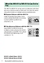
Page 2: ...te Release with the WR T10 A WR T10 wireless transmitter can be used to release the shutter on a camera to which a WR R11a WR R11b is attached 0 8 Simultaneous Release with the WR T10 Attach WR R11a WR R11b units to multiple cameras and press the shutter release button on the WR T10 to release the shutters simultaneously on all cameras 0 11 WR R11a Model Name N2012 WR R11b Model Name N1839 Whatthe...

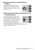
Page 3: ...lled by a single camera 0 13 Using the WR R11a WR R11b with WR 1 Wireless Remote Controllers In combination with a WR 1 wireless remote controller the WR R11a WR R11b can be used for interval timer photography in which the camera takes a selected number of shots automatically at preset intervals and long time exposures as well as for simultaneous and synchronized release 0 18 ...

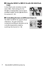
Page 4: ...ttings for the SB 5000 including flash control mode and flash output can be adjusted from the camera 0 24 Controlling Devices on Different Channels The WR R11a WR R11b supports three channels 5 10 and 15 Devices connected via different channels can be controlled separately simply by switching the channel 0 34 15CH 15CH 15CH 10CH 10CH 10CH 5CH 5CH 5CH ...

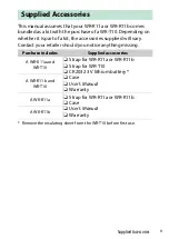
Page 5: ...ry Contact your retailer should you notice anything missing Remove the insulating sheet from the WR T10 before first use Supplied Accessories Purchase includes Supplied accessories A WR R11a and WR T10 Strap for WR R11a or WR R11b Strap for WR T10 CR2032 3 V lithium battery Case User s Manual Warranty A WR R11b and WR T10 A WR R11a Strap for WR R11a or WR R11b Case User s Manual Warranty A WR R11b...

Page 6: ... for use with cameras with a ten pin remote terminal the WR R11b for use with cameras with an accessory terminal Symbols The following symbols are employed in this manual Use them to help locate the information you need A For Your Safety For Your Safety contains important safety instructions Be sure to read them before using the product For more information see For Your Safety 0 ix About This Manu...

Page 7: ...ess Regulation Data xiii Notices xvi Getting Started 1 Parts of the Controller 1 WR R11a 1 WR R11b 1 WR T10 2 Attaching the WR R11a WR R11b Transceiver 5 Attaching the WR R11a 5 Attaching the WR R11b 6 Using the WR R11a WR R11b with the WR T10 The Basics 8 Pairing the WR R11a WR R11b and WR T10 8 Taking Pictures 10 Table of Contents ...

Page 8: ...1a WR R11b 13 Using the WR R11a WR R11b with Other Devices 18 Using the WR R11a WR R11b with WR 1 Wireless Remote Controllers 18 Using the WR R11a WR R11b with SB 5000 Flash Units 24 Channel Selection 34 Technical Notes 35 Status LEDs 35 WR R11a WR R11b 35 WR T10 39 Specifications 40 WR R11a WR R11b Wireless Remote Controller 40 WR T10 Wireless Remote Controller 41 ...

Page 9: ...CAUTION Failure to observe the precautions marked with this icon could result in injury or property damage A WARNING Do not use while walking or operating a vehicle Failure to observe this precaution could result in accidents or other injury Do not disassemble or modify this product Do not touch internal parts that become exposed as the result of a fall or other accident Failure to observe these p...

Page 10: ...ts constitute a choking hazard Should a child swallow any part of this product seek immediate medical attention Do not entangle wrap or twist the straps around your neck Failure to observe this precaution could result in accidents Do not use batteries not specifically designated for use with this product Failure to observe this precaution could result in fire or electric shock A CAUTION Turn this ...

Page 11: ...Batteries Do not mishandle batteries Failure to observe the following precautions could result in the battery leaking overheating rupturing or catching fire Do not attempt to recharge the battery Do not expose batteries to flame or excessive heat Do not disassemble Do not short circuit the terminals by touching them to necklaces hairpins or other metal objects Do not expose batteries or the produc...

Page 12: ...ion or deformation Failure to observe this precaution could result in the battery leaking overheating rupturing or catching fire Insert the battery in the correct orientation Failure to observe this precaution could result in the battery leaking overheating rupturing or catching fire When batteries are no longer needed insulate the terminals with tape Overheating rupture or fire may result should ...

Page 13: ...Interference Statement Note This equipment has been tested and found to comply with the limits for a Class B digital device pursuant to part 15 of the FCC Rules These limits are designed to provide reasonable protection against harmful interference in a residential installation This equipment generates uses and can radiate radio frequency energy and if not installed and used in accordance with the...

Page 14: ...n the microwave range while being used Whereas high levels of RF can produce health effects by heating tissue exposure of low level RF that does not produce heating effects causes no known adverse health effects Many studies of low level RF exposures have not found any biological effects Some studies have suggested that some biological effects might occur but such findings have not been confirmed ...

Page 15: ...available at the following internet addresses WR T10 https imaging nikon com support pdf DoC_WR T10 pdf WR R11a https imaging nikon com support pdf DoC_N2012 pdf WR R11b https imaging nikon com support pdf DoC_N1839 pdf Notice for Customers in Singapore Notice for Customers in Malaysia Notice for Customers in Australia and New Zealand This device complies with radio frequency regulations The conte...

Page 16: ... not required for export to countries other than the following which as of this writing are subject to embargo or special controls Cuba Iran North Korea Sudan and Syria list subject to change Notice for Customers in Canada CAN ICES 3 B NMB 3 B Notices for Customers in Europe This symbol indicates that electrical and electronic equipment is to be collected separately The following apply only to use...

Page 17: ... R11b Parts of the Controller q w e t y r u 1 Red LED 2 Channel selector 3 Green LED 4 Pairing button 5 Strap eyelet 6 Locking screw 7 Mounting mark d y t q w e r 1 Red LED 2 Channel selector 3 Green LED 4 Pairing button 5 Strap eyelet 6 Mounting mark d ...

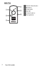
Page 18: ...2 Parts of the Controller WR T10 t r y q w e 1 Shutter release button 2 Fn button 3 Strap eyelet 4 Red LED 5 Channel selector 6 Pairing button ...

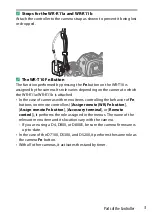
Page 19: ...attached In the case of cameras with menu items controlling the behavior of Fn buttons on remote controllers Assign remote WR Fn button Assign remote Fn button Accessory terminal or Remote control it performs the role assigned in the menus The name of the relevant menu item and its location vary with the camera If you are using a D4 D800 or D800E be sure the camera firmware is up to date In the ca...

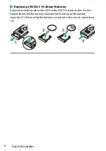
Page 20: ...32 3 V Lithium Batteries Replace the battery when the LED for the WR T10 starts to dim Insert a fingernail behind the battery chamber latch and open the battery chamber q Ensure that the battery is inserted in the correct orientation e q w e r ...

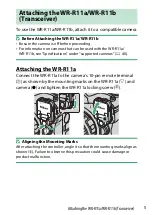
Page 21: ... Specifications under supported cameras 0 40 Attaching the WR R11a Connect the WR R11a to the camera s 10 pin remote terminal q as shown by the mounting marks on the WR R11a d and camera b and tighten the WR R11a locking screw w D Aligning the Mounting Marks After attaching the controller angle it so that the mounting marks align as shown e Failure to observe this precaution could cause damage or ...

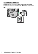
Page 22: ...6 Attaching the WR R11a WR R11b Transceiver Attaching the WR R11b Connect the WR R11b to the camera s accessory terminal as shown by the mounting marks on the WR R11b d and camera c ...

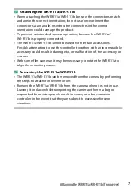
Page 23: ... Forcibly attempting to use the controller together with an incompatible accessory could result in damage to or malfunction of the accessory or camera With some film cameras it may be necessary to rotate the WR R11a to align the mounting marks A Removing the WR R11a WR R11b The WR R11a WR R11b can be removed from the camera by performing the steps to attach it in reverse order Remove the WR R11a W...

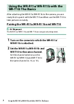
Page 24: ...tures remotely Pairing the WR R11a WR R11b and WR T10 D At Shipment The WR R11a WR R11b and WR T10 are not paired at shipment 1 Turn on the camera to which the WR R11a WR R11b is attached 2 Set the WR R11a WR R11b and WR T10 to the same channel Set the channel selectors on the WR R11a WR R11b and WR T10 to the same channel 5 10 or 15 Using the WR R11a WR R11b with the WR T10 The Basics ...

Page 25: ...at Step 3 A Channel Selection Devices that are not on the same channel cannot be paired Changing the channel on either device once pairing is complete will interrupt the connection The connection will resume when the devices are again set to the same channel the pairing process need not be repeated A Ending Pairing To end pairing keep the WR R11a WR R11b pairing button pressed for about 3 seconds ...

Page 26: ...a WR R11b is attached The shutter release button on the WR T10 performs the same functions as the camera shutter release button whether pressed halfway or all the way down 1 Frame the shot on the camera to which the WR R11a WR R11b is attached Use of a tripod is recommended 2 Press the WR T10 shutter release button halfway to focus 3 Press the WR T10 shutter release button the rest of the way down...

Page 27: ...meras to which WR R11a WR R11b controllers have been attached Simultaneous Release with the WR T10 A single WR T10 can be paired with multiple WR R11a WR R11b controllers and used to simultaneously release the shutters on multiple cameras with one press of the WR T10 s shutter release button ApplicationsfortheWR R11a WR R11b and WR T10 ...

Page 28: ...R T10 The Basics 0 8 Set all WR R11a WR R11b controllers to the same channel Here all controllers are set to Channel 10 Pairing is also available with WR R10 controllers Simultaneous release with a mix of WR R11a WR R11b and WR R10 controllers is also supported 2 Take pictures Pressing the shutter release button on the WR T10 releases the shutters on all cameras to which paired WR R11a WR R11b con...

Page 29: ...he shutter release button is pressed is referred to as the master camera while the cameras that release their shutters in response are referred to as remote cameras The cameras that can function in the role of master are the D780 mirrorless cameras and cameras compatible with the WR R11a Other cameras can serve as remote cameras Method Description Pairing Simply press the pairing buttons on two co...

Page 30: ...usly just as you would when pairing the devices with a WR T10 1 Turn on the cameras to which the WR R11a WR R11b controllers are attached 2 Set the WR R11a WR R11b controllers to the same channel Set the channel selectors on the WR R11a WR R11b controllers to the same channel 5 10 or 15 Here all controllers are set to Channel 10 ...

Page 31: ...airing devices place them close together To synchronize release with further cameras pair the master with the WR R11a WR R11b for each of the remote cameras Pairing is also available with WR R10 controllers Synchronized release with a mix of WR R11a WR R11b and WR R10 controllers is also supported 4 Take pictures Releasing the shutter on the master camera releases the shutters on all cameras to wh...

Page 32: ...t to other cameras Pairing is not required for wireless PIN connections 1 Turn on the cameras to which the WR R11a WR R11b controllers are attached 2 Set the WR R11a WR R11b controllers to the same channel Set the channel selectors on the WR R11a WR R11b controllers to the same channel 5 10 or 15 Here all controllers are set to Channel 10 3 On the master camera select Wireless remote WR options Li...

Page 33: ...mote cameras In the setup menu select Wireless remote WR options Link mode PIN and enter the PIN code selected in Step 4 A connection will be established automatically when you press J To synchronize release with further cameras enter the PIN code on each device to which a WR R11a WR R11b is attached 6 Take pictures Releasing the shutter on the master camera releases the shutters on all cameras wi...

Page 34: ...erval timer photography in which the camera automatically takes pictures automatically at preset intervals and long time exposures as well as for simultaneous and synchronized release For more information see the documentation for the WR 1 When reading the documentation for the WR 1 replace all references to the WR R10 with the WR R11a WR R11b When used as a transmitter the WR 1 should be placed i...

Page 35: ...or more remote cameras 0 13 Remote Fn Button The Fn button on a transmitting WR 1 performs the function assigned by cameras to which the WR R11a WR R11b controllers are attached The Fn button functions in the same way as the button on the WR T10 0 3 This feature is available only when the WR 1 functions independently as a transmitter It is not available when the WR 1 is mounted on a camera Interva...

Page 36: ... pressed state for long time exposures or to take single shots in burst release modes This feature is available only when the WR 1 functions independently as a transmitter It is not available when the WR 1 is mounted on a camera Release Delay Delay release of the shutter on cameras to which receiving WR 1 controllers are attached ...

Page 37: ...1 1 Use the WR 1 as a transmitter or receiver Slide the Tx Rx OFF switch on the WR 1 to Tx to use the WR 1 as a transmitter or to Rx to use it as a receiver 2 Set the WR R11a WR R11b and WR 1 to the same channel The channel for the WR R11a WR R11b can be chosen using the channel selector To choose a channel for the WR 1 press E or G When using the WR 1 with the WR R11a WR R11b choose channel 5 10 ...

Page 38: ...Using the WR R11a WR R11b with Other Devices 3 Select PAIRING for LINK MODE in the WR 1 menus 4 Highlight PAIRING in the WR 1 menus and press 2 5 Turn on the camera to which the WR R11a WR R11b is attached ...

Page 39: ...e pairing button on the WR R11a WR R11b When pairing devices place them close together The red and green LEDs on the WR R11a WR R11b will flash on and off in sequence when pairing is complete The WR 1 will display a message and the red and green LEDs will flash on and off in sequence Press MENU to exit when the menus are displayed ...

Page 40: ...more information on available features and on adjusting settings see the documentation for the camera and SB 5000 When reading the documentation for the SB 5000 replace all references to the WR R10 with the WR R11a WR R11b For use with radio remote control the SB 5000 must either be paired with the WR R11a WR R11b or connected in PIN mode Pairing Press the pairing button on the WR R11a WR R11b to ...

Page 41: ...about 30 m 98 ft It offers more flexibility in lighting choices and frees you from fretting over flash placement Support for Multiple Remote Flash Units Radio AWL allows simultaneous control of up to 18 flash units arranged freely in up to 6 groups Two Way Communication The camera provides real time updates on the status and settings of remote flash units Flash settings can also be adjusted from t...

Page 42: ...ra to which the WR R11a WR R11b is attached 2 Set the WR R11a WR R11b to the desired channel Here we select Channel 15 3 Select Radio AWL for Flash control Wireless flash options in the camera photo shooting menu 4 Select Pairing for Wireless remote WR options Link mode in the camera setup menu ...

Page 43: ...cycle through remote modes until radio control remote mode is displayed Keep cycling until the a icon is displayed 7 Set the flash unit to the same channel as the WR R11a WR R11b Press the MENU button highlight CHANNEL in the wireless item tab and press OK Highlight the channel selected in Step 2 and press OK Here we select Channel 15 ...

Page 44: ...PAIR and press OK EXECUTE will be highlighted 10 Press the OK button on the flash unit and the pairing button on the WR R11a WR R11b Wait no longer than about a second between pressing the OK button on the flash unit and the pairing button on the WR R11a WR R11b If desired the pairing button on the WR R11a WR R11b can be pressed before the OK on the flash unit ...

Page 45: ...omplete when the green LED on the WR R11a WR R11b lights the flash unit LINK indicator turns green and the flash unit displays the message PAIRING COMPLETE You will not need to perform pairing again when connecting the devices in future If pairing fails for example because you waited too long between pressing the buttons on the flash unit and WR R11a WR R11b the flash unit will display the message...

Page 46: ...is attached 2 Set the WR R11a WR R11b to the desired channel Here we select Channel 15 3 Select Radio AWL for Flash control Wireless flash options in the camera photo shooting menu 4 Go to the camera setup menu select Wireless remote WR options Link mode then highlight PIN and press 2 A PIN entry dialog will be displayed ...

Page 47: ... J Enter a four digit number of your choice There is no need to re enter the PIN in future 6 Rotate the flash unit power switch to REMOTE 7 Press the wireless setting button to cycle through remote modes until radio control mode is displayed Keep cycling until the a icon is displayed ...

Page 48: ...nel as the WR R11a WR R11b Press the MENU button highlight CHANNEL in the wireless item tab and press OK Highlight the channel selected in Step 2 and press OK Here we select Channel 15 9 Choose PIN mode Highlight LINK MODE in the wireless item tab and press OK Highlight PIN and press OK ...

Page 49: ...o enter the PIN pressing H or F to highlight digits and E or G to change Enter the four digit PIN selected in Step 5 Press OK when entry is complete the connection to the camera will be initiated automatically When the connection is established the green LED on the WR R11a WR R11b will light and the LINK indicator on the flash unit will turn green ...

Page 50: ...ired or connected via PIN on different channels can be controlled separately simply by switching the channel For example a WR T10 can be paired with three different WR R11a WR R11b controllers one for each of channels 5 10 and 15 allowing different cameras to be controlled just by changing the channel selectd with the WR T10 Channel Selection WR R11a WR R11b WR T10 WR 1 SB 5000 15CH 15CH 15CH 10CH...

Page 51: ...tions The table below lists the possible states for the LEDs on the WR R11a WR R11b when the controller is used with a WR T10 or WR 1 or another WR R11a WR R11b Device status is shown by the green and red LEDs in combination The following also applies in the case of cameras that do not have a Flash control Wireless flash options item in the photo shooting menu Status LEDs Status color Description ...

Page 52: ...f Flashes rapidly 2 flashes about twice a second The Fn button on a WR T10 or on a WR 1 configured independently as a transmitter is pressed Flashes at approximately 2 second intervals Off The camera standby timer is off Flashes rapidly about twice a second Off The camera standby timer is on Flashes rapidly about 5 times a second Off Ready to pair Flash on and off in rapid succession followed by g...

Page 53: ...n before the green LED lights for about a second Flickers flashes about 20 times a second Pairing is ending the green and red LEDs will light twice simultaneously when pairing ends Red LED On The shutter release button has been pressed all the way down 1 Flashes rapidly about twice a second The shutter release button has been pressed halfway 1 Flashes rapidly 2 flashes about twice a second The Fn ...

Page 54: ...he same PIN and another camera is connected to an SB 5000 flash unit A Disabling the LEDs If the camera features a Wireless remote WR options item in the setup menu the LEDs on the WR R11a WR R11b can be disabled by selecting Off for LED lamp A First Use It may take some time for the LEDs to begin flashing when the camera is first turned on after the WR R11a WR R11b is attached but photography can...

Page 55: ...se button is pressed halfway Lights for about 2 seconds and then dims The shutter release button is pressed all the way down Flashes 2 times about twice a second The Fn button is pressed About 7 long flashes Ready to pair Lights once and then lights briefly 3 times in succession Battery inserted ...

Page 56: ...OOLPIX P950 Cannot be used with an MB D100 attached to the D100 Wireless Channels 5 2 425 GHz 10 2 450 GHz 15 2 475 GHz Maximum output power EIRP WR R11a 6 4 dBm WR R11b 7 5 dBm Range line of sight 50 m 164 ft between WR R11a WR R11b wireless remote controllers at a height of 1 2 m 3 9 ft Without interference Range may vary with signal strength operating environment and presence or absence of obst...

Page 57: ...ox 34 5 26 5 14 mm 1 4 1 1 0 6 in width height depth Weight WR R11a Approx 16 g 0 6 oz body only WR R11b Approx 8 g 0 3 oz body only Type Type WR T10 Wireless Channels 5 2 425 GHz 10 2 450 GHz 15 2 475 GHz Maximum output power EIRP 8 85 dBm Range line of sight 20 m 66 ft from WR T10 to WR R11a WR R11b at a height of 1 2 m 3 9 ft Without interference Range may vary with signal strength operating en...

Page 58: ...environment Where the operating temperature range for this product differs from that for the camera restrict the use of this product to whichever range is narrower Power source Batteries One CR2032 3 V lithium battery Battery life Number of shots Approx 10 000 releases Operating environment Temperature 20 C 50 C 4 F 122 F Humidity 85 or less no condensation Dimensions weight Dimensions Approx 28 6...

Page 59: ......
Page 60: ...I01 11 6MBJ2711 01 No reproduction in any form of this manual in whole or in part except for brief quotation in critical articles or reviews may be made without written authorization from NIKON CORPORATION ...

Reviews: