


38
3. OPERATING PROCEDURE : Bifocal and Trifocal Lens Measurement
3.5
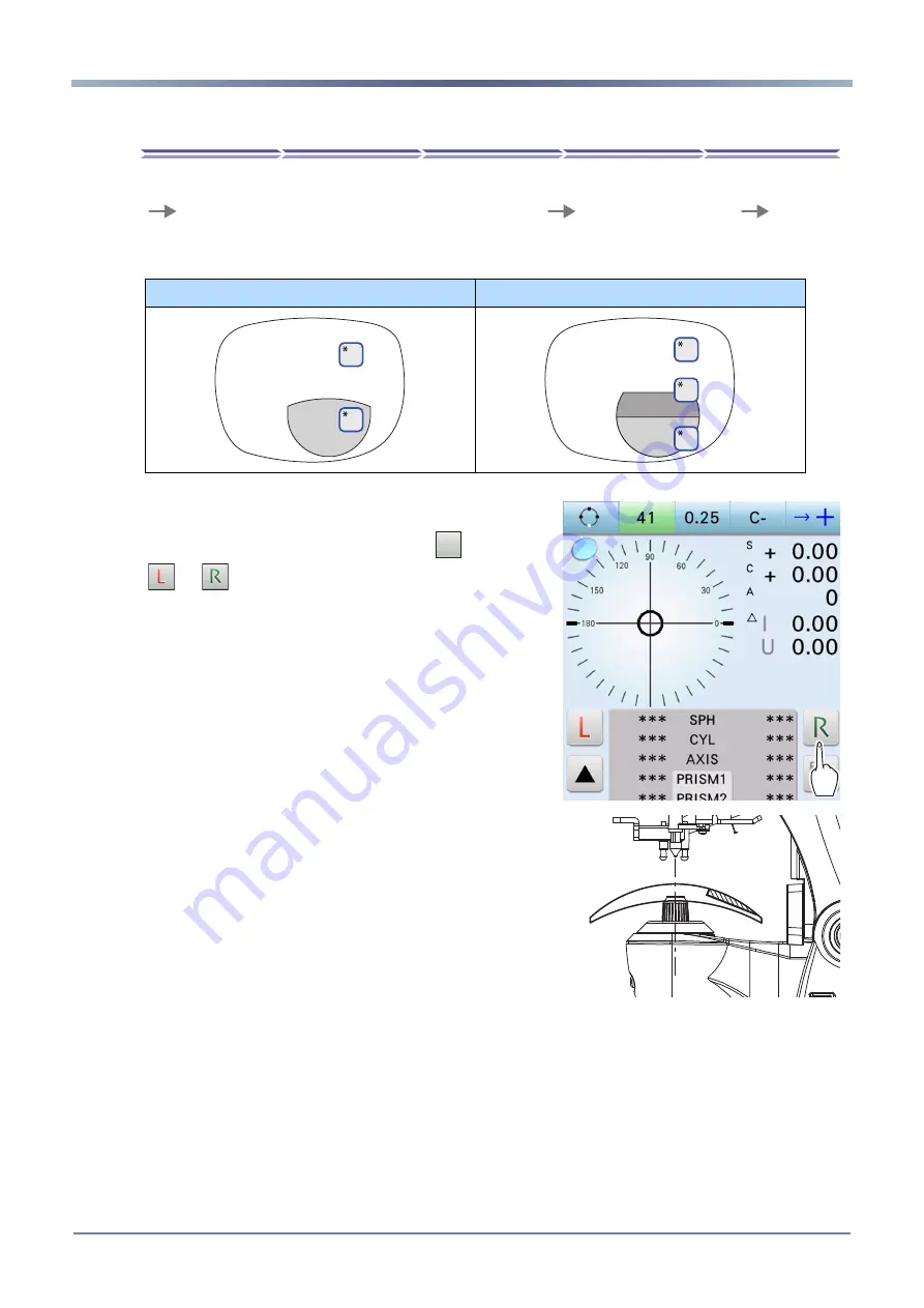
Bifocal and Trifocal Lens Measurement
Bifocal lenses (or trifocal lenses) can be measured successively in the order of distance portion
*1
near portion
*2
(for trifocal lenses, distance portion
*1
intermediate portion
*2
near por-
tion
*3
).
Above lenses are measured on the auto measurement screen or normal measurement screen.
1
Specify the lens side if necessary.
Press the R/L measurement select button
to switch to
or
.
The selected button blinks in green to indicate that
the corresponding lens is being measured.
2
Bring the distance portion of the lens onto the
nosepiece with the concave side facing down.
Bifocal lens
Trifocal lens
±
²
±
²
³
1707141668223 承認済
Uncontrolled copy when printed.
Summary of Contents for LM-7
Page 1: ...LM 7 LM 7P AUTO LENSMETER OPERATOR S MANUAL 1707141668223 Uncontrolled copy when printed...
Page 6: ...4 1707141668223 Uncontrolled copy when printed...
Page 12: ...10 1 SAFETY PRECAUTIONS Labels and Symbols 1707141668223 Uncontrolled copy when printed...
Page 88: ...86 4 CONNECTION AND SETTINGS Parameter Settings 1707141668223 Uncontrolled copy when printed...


