Nidec Profinet Module User Manual Download Page 11


6.  Packet Structures 

NOTE


Some soft starters do not support some functions. 
The following functions are only available with Digistart D3 soft starters: 

parameter management, dual motor control, digital inputs, jog, current measurement in 

amperes, power information, warnings. 


6.1  Ensuring Safe and Successful Control 

Data written to the Profinet Module will remain in its registers until the data is overwritten or the module is 

reinitialised. The Profinet Module will not transfer successive duplicate commands to the soft starter. 

NOTE


If the soft starter is started via fieldbus communications but stopped via the keypad or a remote 

input, an identical start command cannot be used to restart the starter. 

In order to operate safely and successfully in an environment where the soft starter may also be 

controlled via the keypad or the remote inputs (as well as via fieldbus communications), a control 

command should be immediately followed by a status query to confirm the command has been actioned. 


6.2  Control Commands (Write Only) 

Use the following structures to send a control command to the soft starter: 

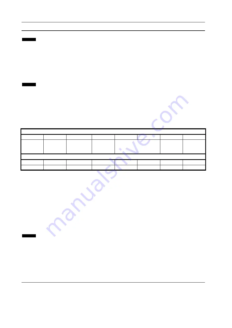
Table 6-1 Control I/O data structure 

Byte 0 

Bit 7 

Bit 6 

Bit 5 

Bit 4 

Bit 3 

Bit 2 

Bit 1 

Bit 0 

Reserved


Reserved


Reserved


Quick stop 

(coast to 

stop) 

Motor set 

Reserved


Reserved


Byte 1 

Bit 7 

Bit 6 

Bit 5 

Bit 4 

Bit 3 

Bit 2 

Bit 1 

Bit 0 

Reserved


Reserved


Reserved


Reserved


Reset 

Reserved


Reserved


Fwd run 


6.2.1  Motor Set Bits 

Selects which parameter set to use when starting: 

0 = selected from soft starter remote input (programmable input must be set to 'Motor Set Select') 

1 = soft starter primary motor set (ensure soft starter programmable input is not set to 'Motor Set Select') 

2 = soft starter secondary motor set (ensure soft starter programmable input is not set to 'Motor Set 

Select') 

3 = 

Reserved


6.2.2  Quick Stop Bit 

When Fwd run bit changes from 1 to 0: 

0 = stop action will be a soft stop (as selected on the soft starter). 

1 = stop action will be a quick stop (ie coast to stop). 

NOTE


The Quick stop bit must be set to 0 before the soft starter can perform a start. 


6.2.3  Forward Run 

When Forward run changes from 0 to 1, the soft starter will start according to the Motor set setting. 
When Forward run changes from 1 to 0, the soft starter will stop according to the Quick stop setting. 


Profinet Module: User Guide 


11 

Issue: B 

www.nidec.com 


Summary of Contents for Profinet Module

Page 1: ......

Page 2: ...g In the interests of commitment to a policy of continuous development and improvement the manufacturer reserves the right to change the specification of the product or its performance or the content...

Page 3: ...Configuration 8 4 1 Ethernet Device Configuration Tool 8 5 Operation 10 5 1 Device Classification 10 5 2 Master Configuration 10 5 3 LEDs 10 6 Packet Structures 11 6 1 Ensuring Safe and Successful Con...

Page 4: ...lable for Profinet Modbus TCP and Ethernet IP networks The Profinet Module operates at the application layer Lower levels are transparent to the user Familiarity with Ethernet protocols and networks i...

Page 5: ...e top and bottom retaining clips to secure the module to the starter 5 Insert the network connector 6 Apply control power to the soft starter Figure 2 1 Attach the module to the starter 1 2 3 10178 B...

Page 6: ...ote See the soft starter user manual for parameter details Figure 3 1 Profinet Module connections Digistart D2 Digistart D3 15633 A 1 3 2 15634 A 1 3 2 Digistart D2 Digistart D3 Remote mode CSL DI2 St...

Page 7: ...st communication relation RTA Real time acyclic protocol Flexible RT_CLASS_2 Real time cyclic protocol Class 2 synchronised RT_CLASS_UDP Unsynchronised cross subnet communication between different sub...

Page 8: ...ice Configuration Tool can be downloaded from www nidec com To configure the device using the Ethernet Device Configuration Tool 1 Attach the module to a soft starter 2 Connect one Ethernet port on th...

Page 9: ...7 To set a static IP address click Configure then select Set IP address 8 To configure a device name click Configure then select Device Name Profinet Module User Guide 9 Issue B www nidec com...

Page 10: ...on screen icons two graphic bitmap files are available from the website SSPM_N bmp indicates normal mode SSPM_D bmp indicates diagnostic mode 5 3 LEDs Figure 5 1 Feedback LEDs 1 2 T X R X 2 T X R X 1...

Page 11: ...send a control command to the soft starter Table 6 1 Control I O data structure Byte 0 Bit 7 Bit 6 Bit 5 Bit 4 Bit 3 Bit 2 Bit 1 Bit 0 Reserved Reserved Reserved Quick stop coast to stop Motor set Res...

Page 12: ...is value will be 10 times greater than the value displayed on the keypad Ready is set when the soft starter is ready to start the motor On is set when the soft starter is starting running or soft stop...

Page 13: ...s the fault code detailed in the table below 201 Ground fault 23 Parameter out of range 24 Input B trip 26 L1 phase loss 27 L2 phase loss 28 L3 phase loss 29 L1 T1 shorted 30 L2 T2 shorted 31 L3 T3 sh...

Page 14: ...VZC Fail Px 83 Low Control Volts 84 to 98 Internal fault X Contact your local supplier with the fault code X 6 3 4 Motor current Bytes 6 and 7 report motor current in amperes For models D3 1x 0053 B a...

Page 15: ...heck run simulation input A DI4 24V not shorted 6 Tripped 7 Programming mode 8 Jog forward 9 Jog reverse 5 1 Warning 6 0 Unintialised 1 Initialised 7 0 Local control 1 Remote control 8 0 Parameter s h...

Page 16: ...r 3 Changed parameter value will reset registers 2 Changed parameter number and 4 Parameters have changed Always read registers 2 and 4 before reading register 3 3 Bits 10 to 15 of register 4 report t...

Page 17: ...ut byte structure Bit 7 Bit 6 Bit 5 Bit 4 Bit 3 Bit 2 Bit 1 Bit 0 Byte 2 Parameter number to read write Byte 3 Reserved Reserved Reserved Reserved Reserved Write parameter Read parameter Reserved Byte...

Page 18: ...7 0 1 Read starter status Running Byte 0 Byte 1 Byte 2 Byte 3 Byte 4 Byte 5 Byte 6 Byte 7 3 0 Read starter status Tripped trip code 4 Current imbalance Byte 0 Byte 1 Byte 2 Byte 3 Byte 4 Byte 5 Byte...

Page 19: ...ntil all devices are connected Figure 7 2 Line network topology 14695 A NOTE The Profinet Module has an integrated switch to allow data to pass through in line topology The Profinet Module must be rec...

Page 20: ...n turn connects to another module until all devices are connected The final module connects back to the switch Figure 7 3 Ring network topology 14696 A NOTE The network switch must support loss of lin...

Page 21: ...Network RJ45 Settings IP address Automatically assigned configurable Device name Automatically assigned configurable Network Link speed 10 Mbps 100 Mbps auto detect Full duplex Auto crossover Power Co...

Page 22: ......

Reviews: