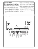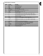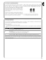
14
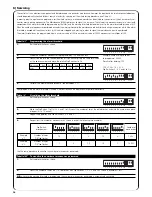
The automation system must be tested by qualified and expert staff who must establish what tests to perform according
to the relative risk.
Testing is the most important part of the whole installation phase. Each single component, e.g. the motor, emergency stop, photocells, etc., may
require a specific test phase; please follow the procedures shown in the respective instructions manuals.
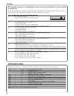
To test the A924 control unit, perform the following operations:
1.
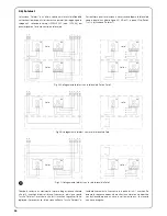
Set the Dip Switches as shown:
(all the functions deactivated and semiautomatic operation)
2.
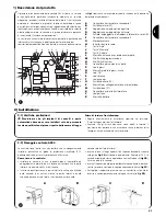
Press the “Open” button (ref. I, fig. 1) and check that:
• the flashing lamp activates
• an opening manoeuvre starts with the acceleration phase
• the door stops moving, preceded by a deceleration phase, when it reaches position A.
3.
Press the “Close” button (ref. K, fig. 1) and check that:
• the flashing lamp activates
• a closing manoeuvre starts
• the door stops moving when it reaches position 0.
4.
Perform an opening manoeuvre and check that the cut-in of a device connected to the:
• “Stop” input immediately stops the door moving
• “Photo” input has no effect
• “Photo2” input stops and inverts the manoeuvre
5.
Perform a closing manoeuvre and check that the cut-in of a device connected to the:
• “Stop” input immediately stops the door moving
• “Photo” input stops and inverts the manoeuvre
• “Photo2” input has no effect
6.
Engage a device connected to the:
• “Stop” input and check that no manoeuvre is performed when a command input is activated
• “Photo” input and check that no manoeuvre is performed when a command input causing a closing manoeuvre is activated
• “Photo2” input and check that no manoeuvre is performed when a command input causing an opening manoeuvre is activated
7.
During both the opening and the closing manoeuvres, stop the door from moving by introducing an obstacle and check that the
manoeuvre inverts before the force indicated by law is exceeded.
8.
Check that the activation of the inputs (of connected) causes a step in the sequence
• for the “Step-by-Step” input: Open – Stop – Close –Stop,
• for the “Open” input: Open – Stop – Open –Stop,
• for the “Close” input: Close – Stop – Close –Stop,
• for the “Partial Open” input: Partial Open – Stop – Close –Stop,
1 2 3 4 5 6 7 8 9 10
11 12
!
5) Selectable functions
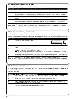
When dip switch programming is Off, the dip switch function allows various other functions to be selected, as shown below:
Switch
1-2
Off Off
=
“Manual” function, i.e.: Man Present
On Off
=
“Semiautomatic” function
Off On
=
“Automatic” function, i.e.: Automatic Closing
On On
=
“Aut Always Closes” function
Switch
3
On
=
Condominium function <Not available in the Manual mode>
Switch
4
On
=
5 s pre-flashing (2 s in the manual mode)
Switch
5
On
=
Close again 5 s after Photo in the automatic mode or close again after Photo in the semiautomatic mode
Switch
6
On
=
“Photo” also in the opening manoeuvre
Switch
7
On
=
Activate Phototest
Switch
8
On
=
Suction pad/Electrical block (On = suction pad Off = electrical block)
Switch
9
On
=
Traffic light in the “one way” mode
Switch
10
On
=
Traffic light in the “two way” mode
N.B.
Naturally, if a Switch is "Off" its associated function is not activated.
4)
Testing
Summary of Contents for Mindy A924
Page 2: ...mindy...
Page 3: ...A924...
Page 19: ...19 Nice reserves the right to modify the products whenever it sees fit...


