


Connection
■
A heat pump must not be connected without the permis-
sion of the electricity supplier and must be connected
under the supervision of a qualified electrician.
■
If a miniature circuit breaker is used this should have
motor characteristic ”D” (compressor operation). For
MCB size see ”Technical Specifications”.
■
When the building is equipped with an earth-fault
breaker the heat pump should be equipped with a separ-
ate one.
■
FIGHTER 1127 does not include an omnipolar circuit
breaker on the incoming power supply. Thus, the install-
ation must be preceded by a safety switch with at least
a 3mm gap.
■
If an insulation test is to be carried out in the building,
disconnect the heat pump.
■
Connect the heat pump to 230 V 1-phase, n
ground via a distribution board with fuses.
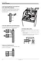
Connection of room temperature sensor RG-20
■
It is important that no other heat source, for example,
lamps, TV or other heat-emitting objects interfere with
the room sensor (155). Curtains should not cover the
sensor.
■
Install in a neutral position where the set temperature is
required. A suitable place is on a free inner wall in a hall
approx. 1.5 m above the floor. However, the sensor must
not be prevented from measuring the correct indoor
temperature, for example, by placing in a niche, between
shelves, behind a curtain, above or close to a heat source
or the like. Also consider any draughts from exterior
doors. Neither must the unit be affected by solar incident
radiation.
■
The conduit should be sealed next to the sensor to pre-
vent a draught in the pipe, which could affect the sensor.
■
The sensor is connected to terminals "1", "4", "5" and
"6" on the relay card’s -E29 (29) terminal block -X30 (30)
(see image).
■
Connection to 4–wire cable, for example, 4 x 0.25 LiYY
(<100 m). The sensor cable must not be routed parallel
with power cable.
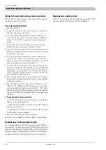
Connecting the outside sensor
■
The outside sensor (15) must be installed in a shaded
location on a wall facing north or north-west, where it
will not be affected by any morning sun. The sensor is
connected by two wires to terminals ”7” and ”8” of
terminal block X30 (30) on the relay card –E29 (29). The
minimum cable cross section is 0.4 mm2 up to 50 metres.
Suitable cable types are EKKX or LiYY.
■
If the outside sensor cable runs close to power cables,
shielded cable must be used. If a conduit is used it must
be sealed to prevent condensation in the sensor capsule.
■
The outdoor sensor should be connected, e.g. to the heat
pump with fixed condensing.
SELV
+
B
A
ñ
B
+
ñ
A
RTG
EXT, EL
UG
1
2
3
4
5
6
7
8
30
86
15
4
1
2
6
SELV
+
B
A
ñ
B
+
ñ
A
RTG
EXT, EL
UG
1
2
3
4
5
6
7
8
30
154
Flödesvakt
155
30
15
F1127 mitsubishi AK 8kW
F1125 mitsubishi (gammalt)
95
68
6
22
9
21
30
29
20
26
13
97
2
164
95
68
6
22
9
21
30
29
26
13
97
14
2
F1127 mitsubishi AK 8kW
F1125 mitsubishi (gammalt)
95
68
6
22
9
21
30
29
20
26
13
97
2
164
95
68
6
22
9
21
30
29
26
13
97
14
2
30
17
FIGHTER 1127
For the Installer
Electrical connections
Summary of Contents for FIGHTER 1127
Page 2: ...LEK LEK LEK LEK LEK LEK LEK LEK LEK LEK...
Page 26: ...Electrical circuit diagram FIGHTER 1127 24 Miscellaneous Technical specifications...
Page 27: ...25 FIGHTER 1127 Miscellaneous Technical specifications...
Page 28: ...FIGHTER 1127 26 Miscellaneous Technical specifications...
Page 29: ...27 FIGHTER 1127 Miscellaneous Technical specifications...
Page 35: ......


