Nibe FIGHTER 1127 Installation And Maintenance Instructions Manual Download Page 16

Pipe connections

General

Pipe installation must be carried out in accordance with cur-
rent norms and directives. FIGHTER 1127 can only operate
up to a return temperature of about 50 °C and an outgoing
temperature of about 60 °C from the heat pump. When
FIGHTER 1127 is not equipped with shut off valves; these
must be installed outside the heat pump to facilitate any fu-
ture servicing.

NOTE

The pipe work must be flushed before the heat pump
is connected, so that any contaminants do not damage

the components parts.

Pipe connection (cooling medium)

When dimensioning the collector, consideration must be
given to the geographical location, type of rock and ground
and the degree of coverage provided by the heat pump.

When installing the collector hose ensure it rises constantly
towards the heat pump to avoid air pockets. If this is not
possible, install high points to vent the air.

All brine pipes in heated rooms must be insulated against
condensation. The expansion tank (EXP) is located on the
incoming pipe before the brine pump.

As the temperature of brine system can fall below 0 °C it
must be protected against freezing down to -15 °C. One litre
of ready mixed brine per meter of collector hose (applies
when using PEM-hose 40 x 2.4 PN 6.3) is used as a guide
value when making the volume calculation.

The expansion tank must be marked to show the type of
antifreeze used.

Shut-off valves should be installed as close to the heat pump
as possible. Fit a particle filter to the incoming pipe.

In the case of connection to an open groundwater system,
an intermediate frost-protected circuit must be provided,
because of the risk of dirt and freezing in the evaporator.
This requires an extra heat exchanger.

Pipe connection (heating medium)

Pipe connections for the heat medium side are made at the
top. All required safety devices, shut-off valves (as close to
the heat pump as possible), and particle filter (supplied) are
fitted.

You should fit either an overflow valve or remove some of
the thermostats when connecting to systems with thermo-
stats on all the radiators (coils).

All heating medium pipes in heated rooms must be insulated
against condensation.

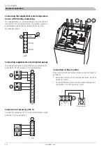
Pump capacity diagrams, heating medium side

Available pressure setup

kPa 

20 

80 

40 

Tillgängligt tryck 

Flöde 

60 

kPa 

20 

80 

40 

Tillgängligt tryck 

Flöde 

60 

kPa 

20 

80 

40 

Tillgängligt tryck 

Flöde 

60 

kPa 

20 

80 

40 

Tillgängligt tryck 

Flöde 

60 

4   k W

FIGHTER 1115 4  

FIGHTER 1115 7  

FIGHTER 1115 8,5  

FIGHTER 1115 10  

FIGHTER 1115 5  

5   k W

7   k W

8 ,5  k W

kPa 

20 

80 

40 

Tillgängligt tryck 

Flöde 

60 

1 0   k W

FIGHTER 1115 13/15  

kPa 

20 

80 

40 

Tillgängligt tryck 

Flöde 

60 

100 

100 

0,07  0,13  0,21 

l/s 

0,27  0,35  0,42  0,48 

0,69 

0,62 

0,55 


0,07  0,13  0,21 

l/s 

0,27  0,35  0,42  0,48 

0,69 

0,62 

0,55 


0,07  0,13  0,21 

l/s 

0,27  0,35  0,42  0,48 

0,69 

0,62 

0,55 


0,07  0,13  0,21 

l/s 

0,27  0,35  0,42  0,48 

0,69 

0,62 

0,55 


0,07  0,13  0,21 

l/s 

0,27  0,35  0,42  0,48 

0,69 

0,62 

0,55 


0,07  0,13  0,21 

l/s 

0,27  0,35  0,42  0,48 

0,69 

0,62 

0,55 


0,2

0,4

0,6

0,8

1,0

1,2

0

Flöde

l/s

0

10

20

30

40

50

60

70

80

90

1

2

3

F1115/1215 - 13(15), 15(17) kW o F1130 - 15, 17 kW o F1320 - 25, 30, 40 kW

Tillgänglig tryckuppsättning, värmebärare

kPa

Tillgängligt tryck

F1115/1215 - 10(12) kW o F1130/1230 - 12 kW o F1320 - 20  kW

0,2

0,4

0,6

0,8

1,0

1,2

0

Flöde

l/s

0

10

20

30

40

50

60

70

80

90

1

2

3

kPa

Tillgängligt tryck

12kW

15/17kW

kPa 

0,1

l/s 

0,2

20

40

Tillgängligt tryck 

Flöde 

0,3

0,4

60

10

30

50

70

kPa 

20

40

60

10

30

50

70

0

20

40

60

10

30

50

70

Tillgängligt tryck 

Flöde 

0,7

0,6

0,5

0,1

0,2

0,3

0,4

0,7

0,8

0,6

0,5

kPa 

20

40

60

10

30

50

70

Tillgängligt tryck 

Flöde 

kPa 

Tillgängligt tryck 

Flöde 


5 kW

FIGHTER 1225 5 

FIGHTER 1225 8 

FIGHTER 1225 10 

FIGHTER 1225 12 

FIGHTER 1225 6 

6 kW

8 kW

10 kW

kPa 

20

80

40

Tillgängligt tryck 

Flöde 

60

12 kW

90

10

70

30

50

0

l/s 

l/s 

l/s 

0,1

0,2

0,3

0,4

0,7

0,8

0,9

0,6

0,5

0,1

0,2

0,3

0,4

0,7

0,8

1,0

0,9

0,6

0,5

0,2

0,4

0,8

1,2

1,0

0,6

l/s 

1

2

3

1

3

3

1

2

3


Available pressure

Flow

FIGHTER 1127 8

Available pressure

FIGHTER 1127 12

Flow

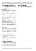
Pump capacity diagrams, collector side

Available pressure setup

FIGHTER 1235 5 

kPa 

10 

80 

40 

Tillgängligt tryck 

Flöde 

60 

0

0,1

0,2

0,3

l/s 

0,4

0,5

0,6

0,7

0,8

1

2

3

20 

30 

50 

70 

FIGHTER 1235 6

kPa 

10 

80 

40 

Tillgängligt tryck 

Flöde 

60 

0,1  0,2  0,3 

l/s 

0,4  0,5  0,6  0,7 

0,9 

0,8 

2

3

20 

30 

50 

70 

FIGHTER 1235 8

kPa 

10 

80 

40 

Tillgängligt tryck 

Flöde 

60 

0,1  0,2  0,3 

l/s 

0,4  0,5  0,6  0,7 

0,9 

0,8 

3

20 

30 

50 

70 

FIGHTER 1135/1235 10

kPa 

10 

80 

40 

Tillgängligt tryck 

Flöde 

60 

0,1  0,2  0,3 

l/s 

0,4  0,5  0,6  0,7 

0,9 

0,8 

20 

30 

50 

70 

Flöde

0

0,1

0,2 0,3

l/s

0,4 0,5 0,6

0,7

1

0,9

0,8

kPa

30

40

110

70

Tillgängligt tryck

90

50

60

80

100

1

2

3

4

FIGHTER 1135/1235 

12/15/17

Available pressure

Flow

FIGHTER 1127 8


4 kW 

5 kW 

7 kW 

8,5 kW 

10, 13, 15 kW 

10 kW 

FIGHTER 1215 4  

kPa 

10 

80 

40 

Tillgängligt tryck 

Flöde 

60 

0,1  0,2  0,3 

l/s 

0,4  0,5  0,6  0,7 

0,9 

0,8 

 1 

20 

30 

50 

70 

FIGHTER 1215 5  

kPa 

10 

80 

40 

Tillgängligt tryck 

Flöde 

60 

0,1  0,2  0,3 

l/s 

0,4  0,5  0,6  0,7 

0,9 

0,8 


20 

30 

50 

70 

FIGHTER 1215 7 

kPa 

10 

80 

40 

Tillgängligt tryck 

Flöde 

60 

0,1  0,2  0,3 

l/s 

0,4  0,5  0,6  0,7 

0,9 

0,8 


20 

30 

50 

70 

FIGHTER 1215 10 

kPa 

120 

60 

Tryckfall 

Flöde 

0,1  0,2  0,3 

l/s 

0,4  0,5  0,6  0,7 

0,9 

0,8 


20 

40 

80 

100 

FIGHTER 1215 8,5 

kPa 

10 

80 

40 

Tillgängligt tryck 

Flöde 

60 

0,1  0,2  0,3 

l/s 

0,4  0,5  0,6  0,7 

0,9 

0,8 


20 

30 

50 

70 

FIGHTER 1130/1230 10 

kPa 

10 

80 

40 

Tillgängligt tryck 

Flöde 

60 

0,1  0,2  0,3 

l/s 

0,4  0,5  0,6  0,7 

0,9 

0,8 

 1 

20 

30 

50 

70 

FIGHTER 1215 10, 13, 15 

kPa 

120 

60 

Tryckfall 

Flöde 

0,1  0,2  0,3 

l/s 

0,4  0,5  0,6  0,7 

0,9 

0,8 


20 

40 

80 

100 

F-1130/1230 6 kW 

F-1130/1230 8 kW 

F-1130/1230 10 kW  

Tillgänglig tryckuppsättning, köldbärarsida  

30 % Etylenglykol 

F-1115 10, 13, 15 kW   F-1130 12, 15, 17

Tillgänglig tryckuppsättning, köldbärarsida

30 % Köldbärarvätska

Flöde

0

0,1

0,2 0,3

l/s

0,4 0,5 0,6

0,7

1

0,9

0,8

kPa

30

40

110

70

Tillgängligt tryck

90

50

60

80

100

1

2

3

4

Available pressure

FIGHTER 1127 12

Flow

FIGHTER 1127

14

For the Installer

Pipe connections

Summary of Contents for FIGHTER 1127

Page 1: ...INSTALLATION AND MAINTENANCE INSTRUCTIONS MOS GB 0737 2 FIGHTER 1127 031153 FIGHTER 1127 2 0 2 1 R 0 LEK...

Page 2: ...LEK LEK LEK LEK LEK LEK LEK LEK LEK LEK...

Page 3: ...n of room temperature sensor RG 20 17 Connecting the outside sensor 17 Connecting the supplied hot water temperature sensor with floating condensing 18 Connecting supplied external circulation pumps 1...

Page 4: ...ominal temperature diff 2 5 C Temperature heat medium in out ____ ____ Pump setting ___ Nominal temperature diff 5 10 C Settings Basic setting Menu Basic setting Menu 60 10b HP min 2 Room 300 10b Add...

Page 5: ...n of flow changes in the refrigerant system Even the external systems brine and heating medium change direction by the external pumps starting for opposite circulation The heat energy is now emitted t...

Page 6: ...p and additional heater when necessary if the latter is fitted B Function keys Channel Selection of the window menu VB Fram 49 50 C Varmvatten 51 C Increase Increase of current value VB Fram 49 50 C V...

Page 7: ...g Addition ready to start if needed Hot water charging cuts in if needed LEDs Continuous light Room heating coo ling Continuous light during hot water char ging Hot water Flashing Steady light Additio...

Page 8: ...om temperature Changing the room temperature manually If you want to temporarily or permanently increase or lower the indoor temperature in relation to the previous heat set ting turn the Increase red...

Page 9: ...ated flow temperature Hot water Indication of the hot water temperature 2a Outdoor 14 C Room 20 5 20 C Outdoor Current outdoor temperature Room Current room temperature Only shown if a room sensor is...

Page 10: ...eating Press the Channel button to continue 4b WW in 37 53 C HW stop 52 C This menu is a sub menu to menu 4 Setting HW stop Press the Increase button in menu 4a A cursor will ap pear within the bracke...

Page 11: ...max levels Sensor placement and pump flow observed 7 HP start 10 HP off HP start Counts the starts of the heat pump cumulative HP off Shows the operating mode HP off HP on HP start in X minutes or Hi...

Page 12: ...nsors The room sensor is used to compensate the deviation in room temperature Guideline values for collectors Recommended collector length must be adjusted according to local conditions The length of...

Page 13: ...by the system is obtained Settings 10a GM GM Degree min P Current value for number of degree minutes For example this value can be changed to accelerate the start of heating cooling production Settin...

Page 14: ...re is then supplemented with EP Selectable operating modes Compressor operation 0 1 step EP drift after acknowledgement 1 16 Cal Out 0 Room 0 Brine In 0 Brine O 0 Cal Out P Calibration of outside sens...

Page 15: ...stops at half R C below Ex ample At R 2 at FIGHTER 1127 and 22 C on RG 20 cooling starts at 24 C and stops at 23 C Default setting is Off In cooling mode with the room sensor RG20 select Cooling On Th...

Page 16: ...ilable pressure setup 0 20 80 40 Fl de 60 1 0 k W 0 20 80 40 Fl de 60 100 100 0 0 07 0 13 0 21 l s 0 27 0 35 0 42 0 48 0 69 0 62 0 55 0 0 07 0 13 0 21 l s 0 27 0 35 0 42 0 48 0 69 0 62 0 55 1 2 3 1 2...

Page 17: ...k VVB ACK is fully charged the shuttle valve VXV switches over to the heating circuit The heat pump is then controlled by the outdoor sensor in combination with the built in flow sensor and room tempe...

Page 18: ...tallation and wiring must be carried out in accord ance with the stipulations in force Supply cables to the heat pump are placed in the cable duct on the left of the unit Cables for external sensors m...

Page 19: ...e for example by placing in a niche between shelves behind a curtain above or close to a heat source or the like Also consider any draughts from exterior doors Neither must the unit be affected by sol...

Page 20: ...rated 22 156 156 X7 Connection of accessory VST 12 Connect the accessory VST 12 to the terminal block X6 6 positions 2 to 5 as illustrated 6 X6 F1127 mitsubishi A 22 21 30 Connection of flow monitor F...

Page 21: ...ling pump are now operating together Let the liquid circu late via the mixing vessel until there are no more air bubbles in the liquid in the return hose Now stop the brine pump by resetting Brine pum...

Page 22: ...lar attention should be given to the level in the brine system when initially using the heat pump Some topping up may be necessary 9 Read the heating medium temperatures WW out and WW in The differenc...

Page 23: ...10 9 8 7 6 5 4 3 2 1 1514 13 12 11 10 8 7 6 5 4 3 2 1 40 C UTETEMPERATUR 10 0 10 5 5 30 40 50 60 70 C FRAMLEDNINGSTEMPERATUR 20 30 F RSKJUTNING V RMEKURVA 2 9 V RMEKURVA V RMEKURVA 5 5 F RSKJUTNING V...

Page 24: ...positions 2 0 2 1 R 0 LEK F1127 mitsubishi AK 8kW 95 68 6 22 9 21 30 29 26 13 97 14 2 K E L K E L 4 86 71 70 89 5 94 35 77 76 16 96 87 LEK 18 17 153 41 33 27 42 7 48 49 65 65 19 FIGHTER 1127 22 Misce...

Page 25: ...Service connection low pressure 42 Expansion valve heating mode 48 Expansion valve cooling mode 49 Safety valve collector side 52 Particle filter 63 Drying filter 65 Contactor compressor start 68 Conn...

Page 26: ...Electrical circuit diagram FIGHTER 1127 24 Miscellaneous Technical specifications...

Page 27: ...25 FIGHTER 1127 Miscellaneous Technical specifications...

Page 28: ...FIGHTER 1127 26 Miscellaneous Technical specifications...

Page 29: ...27 FIGHTER 1127 Miscellaneous Technical specifications...

Page 30: ...98 100 100 100 30 100 67 5 4 71 70 2 0 2 1 R 0 HM flow 49 50 C Hot water 51 C 598 525 525 625 2 0 2 1 R 0 HM flow 49 50 C Hot water 51 C 30 50 1000 75 198 100 100 100 30 100 67 Leave space free to the...

Page 31: ...59526447 230V HEJSAN PC 0017NIB DK 50Hz IP 44 TF 110 Class H Max 10bar 2 5uF 45 0 20 65 0 30 90 0 40 1m A P W LEK GRUNDFOS Type UPS 25 60 130 P N 59526447 230V HEJSAN PC 0017NIB DK 50Hz IP 44 TF 110...

Page 32: ...W Power external circulation pumps 35 28 mm Connection Brine male 28 mm Connection heating medium male 1 9 1 79 kg Refrigerant quantity R407C 0 65 0 48 l s Brine flow 15 23 kPa Pressure drop evaporato...

Page 33: ...ing Incorrect setting of the Curve slope and or Increase reduce room temperature Cause Adjust the setting Action NOTE The product s serial number should always be stated with all correspondence with N...

Page 34: ...low pressure or ice if ice has formed the brine pump 35 will be warm Cause Vent and top up the fluid Wait a few hours Action Brine pump 35 not running Cause Check the brine pump Action Lack of heatin...

Page 35: ......

Page 36: ...6998 E mail info nibeboilers nl www nibeboilers nl V lund Varmeteknik Filial af NIBE AB Brog rdsvej 7 6920 Videb k Tel 97 17 20 33 Fax 97 17 29 33 E mail info volundvt dk www volundvt dk NIBE Systemte...

Reviews: