


3.
Basic Operation
PROGRAMMABLE AC POWER SOURCE
30
Table 3-2 Component Name (Rear)
No. Name
Description
Refer
to
1
External signal input
connector
Used when controlling the voltage value setting
by the external signal (VCA), when
synchronizing the output frequency with the
external signal (SYNC), and when outputting
the amplified external signal (EXT, ADD).
4.17,
4.19,
4.20
2
Monitor output connector
Can observe waveforms of the output voltage
and output current when connected to a unit
such as oscilloscopes.
4.10
3
SYSTEM I/O connector
Not used.
-
4
CONTROL I/O connector
Used to control this product externally by logic
signal and non voltage contact. Also it can
obtain the state of this product with a logic
signal.
It is connected CONTROL IN connector
(No.17) with the attached control cable (25 pin)
when using DIP or RIN.
4.18,
8.1.2,
8.1.3
5 GPIB
connector
or
LAN connector
GPIB or LAN communication interface.
Either one can be chosen when ordering.
6.1.3,
6.1.4
6
RS232 connector
RS232 communication interface.
6.1.2
7
USB connector
USB communication interface.
6.1.1
8
Air outlet
Air outlet for exhausting the heat.
2.2
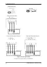
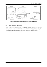
9
Power input terminal
Power input terminal. Power input is 1P2W or
3P3W or 3P4W, either of which can be chosen
when ordering. (The power input 1P2W is not
selectable for DP180LM.) Figure 3-2 shows the
case of power input 3P3W.
2.4
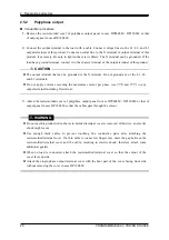
10
Polyphase output terminal
Output terminal for the single-phase three-wire
and three-phase four-wire.
2.5
11
Single-phase output terminal
Output terminal for the single-phase two-wire.
2.5
12
Sensing input terminal
Connect to the load end that is located in the
distance from the main unit to detect its
voltage. Common among the single-phase
two-wire, single-phase three-wire, and
three-phase four-wire output.
4.11
13 Resin-molded cover
Covers the power input terminal, the sensing
input terminal, the single-phase output terminal
and the polyphase output terminal. When no
load is connected, attach the cover so that the
cutout of the cover comes on the upside.
2.4,
2.5
14 Status
output
connector
Output
sync signal in quick change operation
and fluctuation test.
It is used as trigger signal to record waveform.
4.18.1,
4.18.2
15 Quick change sync output
connector
Output sync signal in quick change operation.
It is connected to quick change sync input
connector on DIP.
4.18.1,
4.18.2,
8.1.2
16 CONTROL
SIGNAL
connector
It is connected to CONTROL SIGNAL
connector on DIP or RIN.
4.18.2,
8.1.2,
8.1.3
17 CONTROL
IN
connector
It
is
connected CONTROL I/O connector
(No.4) with the attached control cable (25 pin)
when using DIP or RIN.
4.18.2,
8.1.2,
8.1.3
Summary of Contents for DP060LM
Page 1: ...PROGRAMMABLE AC POWER SOURCE DP060LM DP120LM DP180LM INSTRUCTION MANUAL NF Corporation...
Page 2: ......
Page 3: ...PROGRAMMABLE AC POWER SOURCE DP060LM DP120LM DP180LM INSTRUCTION MANUAL DA00059920 004...
Page 4: ......
Page 19: ...DP060LM DP120LM DP180LM 1 1 Outline 1 1 Overview 2 1 2 Series Lineup 2 1 3 Features 3...
Page 24: ......
Page 224: ......
Page 244: ......
Page 264: ......
Page 300: ...11 Specifications PROGRAMMABLE AC POWER SOURCE 282 Figure 11 4 DP180LM Type5L cabinet...