


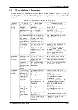


9.2 When a Failure is Suspected
DP060LM/DP120LM/DP180LM
237
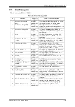
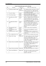
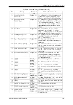
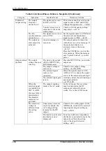
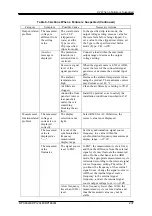
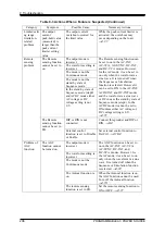
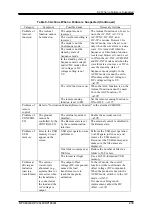
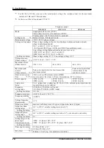
Table 9-3 Actions When a Failure is Suspected (Continued)
Category Symptom
Possible
Cause Necessary
Actions
Output-related
problem
The measured
voltage is
different from
the setting
value.
The waveform is
set to CLP
(clipped sine
wave) and the
Type is set to
Clip (specified
clip ratio mode).
In the specified clip ratio mode, the
output voltage setting means a value for
the waveform before being clipped. To
set a value for the clipped waveform, set
the Type to the specified crest factor
mode (Type: CF).
4.6
An error
message is
displayed.
The protection
function was
activated due to
overload.
Connect a load within the maximum
output range or decrease the output
voltage setting.
Excessive signal
level of the
signal generator.
When the signal source is EXT or ADD,
lower the level of the connected signal
generator or decrease the external input
gain.
The ambient
temperature is
high.
Decrease the ambient temperature when
using the product. The maximum current
may decrease over 40 °C.
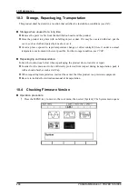
Air filters are
clogged.
Clean the air filters by referring to
10.2
.
Around the front
panel air inlet or
rear panel air
outlet, there is
something
blocking the air
flow.
Install the product so as to satisfy the
installation conditions described in
2.2
.
Measurement
function-related
problem
The measured
voltage or
current is not
displayed
correctly.
The display
selection is not
right.
Select RMS for AC. Otherwise, the
correct value is not displayed.
The measured
value is
displayed as
"----".
It is out of the
synchronization
frequency
measurement
display range.
Set the synchronization signal source
frequency to a value within the
synchronization frequency measurement
display range.
11.12
The measured
value
fluctuates.
The signal source
is set to EXT.
In EXT, the measurement cycle is fixed,
and thus the difference from the external
signal cycle may fluctuate the measured
value. On the other hand, in the ADD
mode, the appropriate measurement cycle
is decided according to the internal signal
source frequency setting. Therefore, if
you know the frequency of the external
signal to use, change the signal source to
ADD, set the internal signal source
frequency to the external signal
frequency, and set the internal signal
source output voltage to zero.
4.20
A low frequency
(less than 10 Hz)
is set.
For a frequency lower than 10 Hz, the
measurement cycle is a fixed value and
thus the measured value may not be
stable.
Summary of Contents for DP060LM
Page 1: ...PROGRAMMABLE AC POWER SOURCE DP060LM DP120LM DP180LM INSTRUCTION MANUAL NF Corporation...
Page 2: ......
Page 3: ...PROGRAMMABLE AC POWER SOURCE DP060LM DP120LM DP180LM INSTRUCTION MANUAL DA00059920 004...
Page 4: ......
Page 19: ...DP060LM DP120LM DP180LM 1 1 Outline 1 1 Overview 2 1 2 Series Lineup 2 1 3 Features 3...
Page 24: ......
Page 224: ......
Page 244: ......
Page 264: ......
Page 300: ...11 Specifications PROGRAMMABLE AC POWER SOURCE 282 Figure 11 4 DP180LM Type5L cabinet...