


4.
Advanced Operation
PROGRAMMABLE AC POWER SOURCE
106
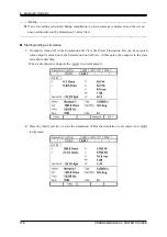
Table 4-5 Simulation Function Steps and Settable Step Parameters
Step Initial
Normal 1
Trans 1
Abnormal
Trans 2
Normal 2
Step
time
— T1 T2 T3 T4 T5
AC
voltage
V0 V1 — V3 —
—(=V1)
Frequency
F0 F1 — F3 —
—(=F1)
Start phase
ON/OFF
P0
ON/OFF
P1
—
ON/OFF
P3
—
ON/OFF
P5
Stop Phase
ON/OFF
Q0
ON/OFF
Q1
—
ON/OFF
Q3
—
ON/OFF
Q5
Trigger
output —
ON/OFF ON/OFF ON/OFF ON/OFF ON/OFF
Sync code
output
S0 S1 S2 S3 S4 S5
Note: "—" means that this parameter cannot be set.
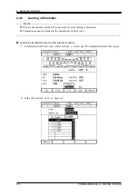
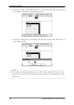
Start phase (Start Phs)
ON or OFF can be selected for the start phase. When ON is selected, the step starts at the specified
start phase. When OFF is selected, the step starts at the phase in which the previous step ended.
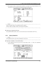
When selecting ON, a numerical entry box in which you can specify the start phase opens.
The start phase can be set at the Normal 1, Normal 2, and Abnormal steps. For other steps, the start
phase is fixed to OFF and cannot be specified.
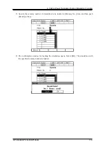
Stop phase (Stop Phs)
ON or OFF can be selected for the stop phase. When ON is selected, the step ends at the specified
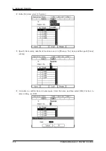
stop phase. If the phase is not the specified stop phase after the Step Time elapsed, the execution
continues the output of that step until reaching the specified Stop Phase, then performs the next step.
When OFF is selected, the step transitions to the next step when the Step Time has elapsed regardless
of the phase. When selecting ON, a numerical entry box in which you can specify the stop phase
opens.
The stop phase can be set at the Normal 1, Normal 2, and Abnormal steps. For other steps, the stop
phase is fixed to OFF and cannot be specified.
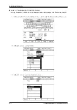
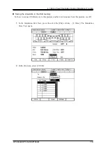
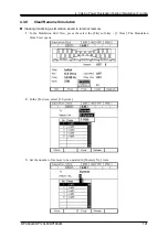
Trigger output (Trig Out)
State output to CONTROL I/O connector. This specifies whether the trigger output presents when the
step starts. Polarity and pulse width of the trigger output complies with the trigger output setting (see
4.3.5
). At the Initial Step, the trigger output cannot be specified and thus no trigger is output.
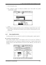
Step sync code output (Code)
State output to CONTROL I/O connector. Code to output while the execution of the step, which is
specified by 2-bit H/L. The step synchronization code can be specified also at the Initial Step.
Summary of Contents for DP060LM
Page 1: ...PROGRAMMABLE AC POWER SOURCE DP060LM DP120LM DP180LM INSTRUCTION MANUAL NF Corporation...
Page 2: ......
Page 3: ...PROGRAMMABLE AC POWER SOURCE DP060LM DP120LM DP180LM INSTRUCTION MANUAL DA00059920 004...
Page 4: ......
Page 19: ...DP060LM DP120LM DP180LM 1 1 Outline 1 1 Overview 2 1 2 Series Lineup 2 1 3 Features 3...
Page 24: ......
Page 224: ......
Page 244: ......
Page 264: ......
Page 300: ...11 Specifications PROGRAMMABLE AC POWER SOURCE 282 Figure 11 4 DP180LM Type5L cabinet...