Shared USB
storage or
printer port
Power
Power
Adapter
USB
Line
RJ-11
TV
A/V
TV receiver
RJ-45
Phone
Jack
Cable/xDSL
Modem
Quick Installation Guide
1
2
3
1
This advanced network device combines the functionality
of an ADSL+ modem, Wi-Fi router, and a four- port
switch. Before setting up the modem/router, you must
have a high speed subscriber line available, known as
DSL. The set up procedure used in this guide is based
on this type of internet connection.
Omnidirectional antennas
DSL:
This asymmetric digital subscriber line port
provides the connection to the ADSL line.
LAN 1/ IPTV:
This IPTV port can be used for
connecting an Internet Protocol TV receiver, and as
a LAN port, when the IPTV feature is not enabled.
LAN ports (2-3):
Connect your laptop or desktop
computers in your network to any of these RJ45
Ethernet ports
LAN 4/WAN:
This port can be used to establish a
WAN link, and as a LAN port, when the former feature
is not being used.
USB 2.0 port:
Multifunctional USB port supports
printer sharing, file sharing and mass storage devices.
WPS/Reset:
Press this button for about one to three
seconds to enable WPS encryption. Press this button
for about seven seconds to restore the device to its
factory default values.
Thank you for purchasing the new
Nova300
ADSL
Modem and Wireless Router from Nexxt Solutions™.
If any of the following items are mismatched, missing
or damaged, please contact the merchant from
whom you purchased the unit for immediate
replacement.
•
AML02304U1
ADSL modem/router
• Network cable
• Telephone cable
• Line filter/splitter
• Power adapter 110/220V
• Quick installation guide
4
5
6
7
8
10
11
12
9
1.
2.
3.
4.
5.
6.
7.
DC input:
Connect the supplied power adapter to
this jack.
Power switch:
Press this button to turn the device
on and off.
8.
9.
Power off your PC, and the DSL modem/router.
Find the optimum location for the router. The best
place is usually at the center or your wireless
network with the antennas in the upright position.
Connect one end of the supplied power adapter to
the AC input jack located on the rear panel of the
router, before plugging the other end to a standard
electrical wall outlet.
USB
LED
indicator
On
The link between the modem/router and a
client device is established through that port
On
The WLAN LED lights up when the wireless
feature is enabled
On
The ADSL connection has been established
Blinking
Blinking
slowly
The device is actively sending or transmitting
data over that port
Blinking The device is actively sending or transmitting
data packets
Off
No active connection is detected in that
LAN port
Off
The wireless connection is disabled
The physical connection failed
Blinking
fast
The device is synchronizing
Status
Description
LAN 1/
ITV, 2, 3, 4
/WAN
DSL
WLAN
LED
indicator
The system is operating properly
On
Off
On
Off
On
Off
The LED starts blinking during WPS
authentication on a client, which is enabled
through the device button or interface
Blinking
Blinking
Solid
or off The system fails or is not operating properly
On
The client is connected successfully
Off
When no wireless clients are connected,
the WPS turns off after two minutes
The device is powered on
The device is powered off
The USB port is active
The USB port is not in use
The device is actively connected to
the internet
No internet connection is detected
Status
Description
SYS
WPS
POWER
INTERNET
1 unit
1 unit
2 units
1 unit
1 unit
1 unit
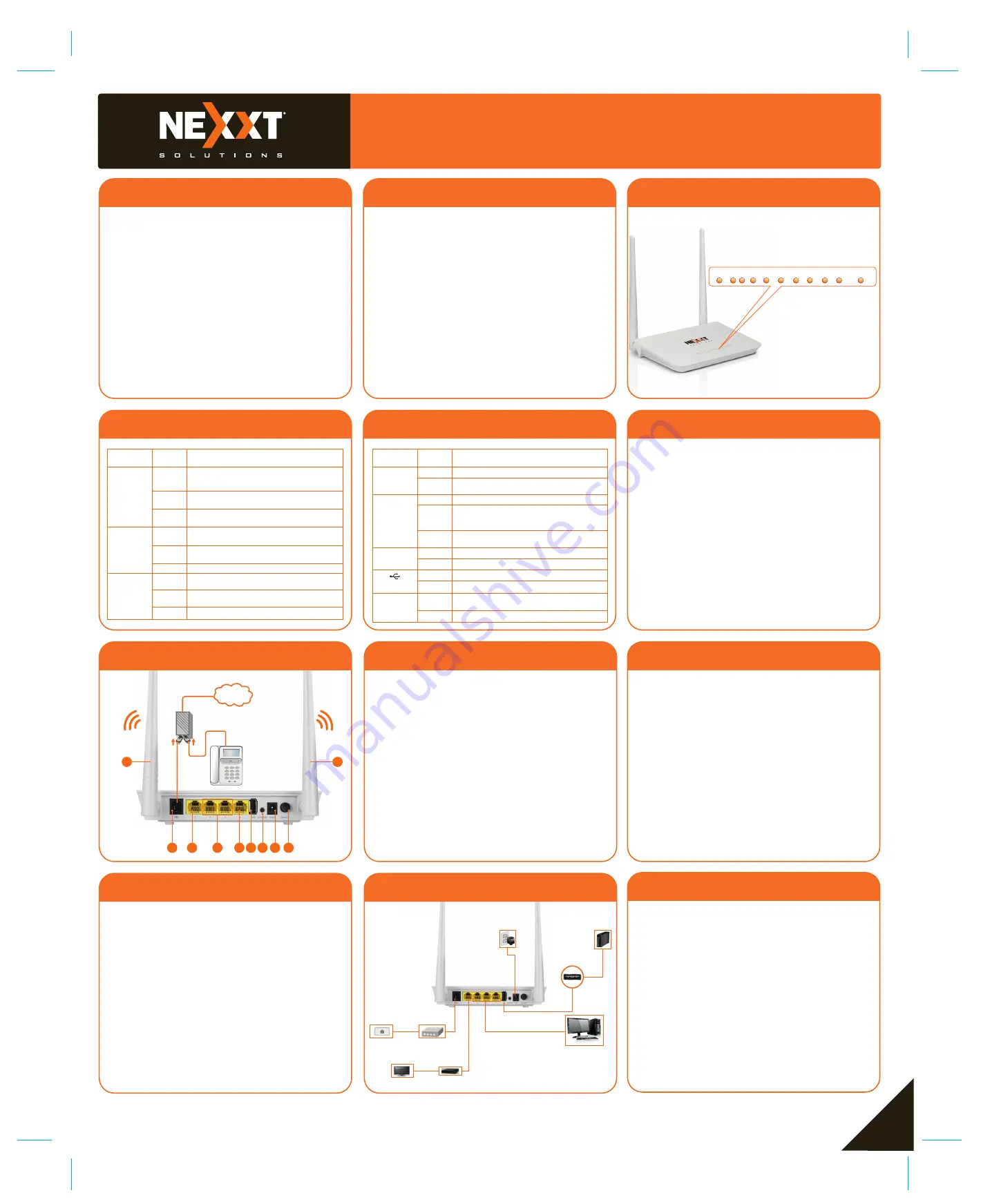
LED indicators on the front panel provide information
about network activity, the connection and link status
of the ports in real time. They also facilitate activity
monitoring and troubleshooting the performance of
the device.
Front panel
The rear panel provides the physical connectors
for power and the client network devices.
Back panel
After all connections have been properly done,
access the modem/router web interface by typing
http://192.168.1.1
on the address bar. Press
enter to continue.
The login window will come up. The system will then
prompt you to enter the default user name and
password. Type
admin
in both cases. Click
Login
to continue.
Modem/router configuration
Hardware installation
Product layout
Preliminary steps
Port 1 can be used interchangeably as an IPTV or
LAN connection.
Port 4 can be used interchangeably as a LAN or
WAN connection.
Note:
•
•
INTERNET
1
1
2
3
4
5 6 7 8 9
1.
2.
3.
1.
2.
Connect your network devices to the LAN ports of
the router.
Connect the ADSL line from the service provider to
the single port of the splitter using one of the RJ-11
cables provided. From the dual port side, use the
second RJ-11 cable to connect to the DSL jack on
your modem/router. The open available port then
can be used to connect a phone line.
Finally, power on the modem/router and your PC.
The PWR, SYS, DSL, WLAN and any active LAN
LEDs will initially light up on the modem when the
hardware connections have been successfully
completed, as shown in the diagram below.
4.
5.
6.
7.
4/WAN
WLAN SYS WPS PWR USB INTERNET
2 3 1/iTV DSL


