


ESP302 Controller
Start-Up Manual
33
A1270B1 - EDH0411En1021 – 02/20
6.2
Axes
6.2.1
Digital Encoder Inputs
All digital encoder inputs are RS-422 standard compliant:
•
All digital encoder signals are not isolated, but are referenced to the electrical
ground (GND).
•
Encoder signals must be differential pairs. Encoder inputs have a terminating
impedance of 120 Ω.
•
Inputs are always routed on differential pairs. For a high level of signal integrity, we
recommend using shielded twisted pairs of wires for each differential signal.
•
Encoder power supply is +5 V @ 250 mA maximum (referenced to the electrical
ground) and is sourced directly by the driver board. The +5 V power supply is low
noise (approximately 20 mVpp), fuse protected up to 500 mA/plug, and supplies
5.13 V without load.
6.2.2
Digital Servitudes
All servitude inputs are TTL compatible:
•
All servitude inputs are not isolated, but are referenced to the electrical ground
(GND).
•
Input levels must be between 0 V and +5 V.
All servitude inputs are refreshed synchronously with the ESP302 servo rate.
All servitude inputs are identical.
All servitude inputs expect normally closed sensors referenced to ground (input is
activated if the sensor is open) and have internal 2.2 kΩ pu
ll up resistors to the +5 V.
6.2.3
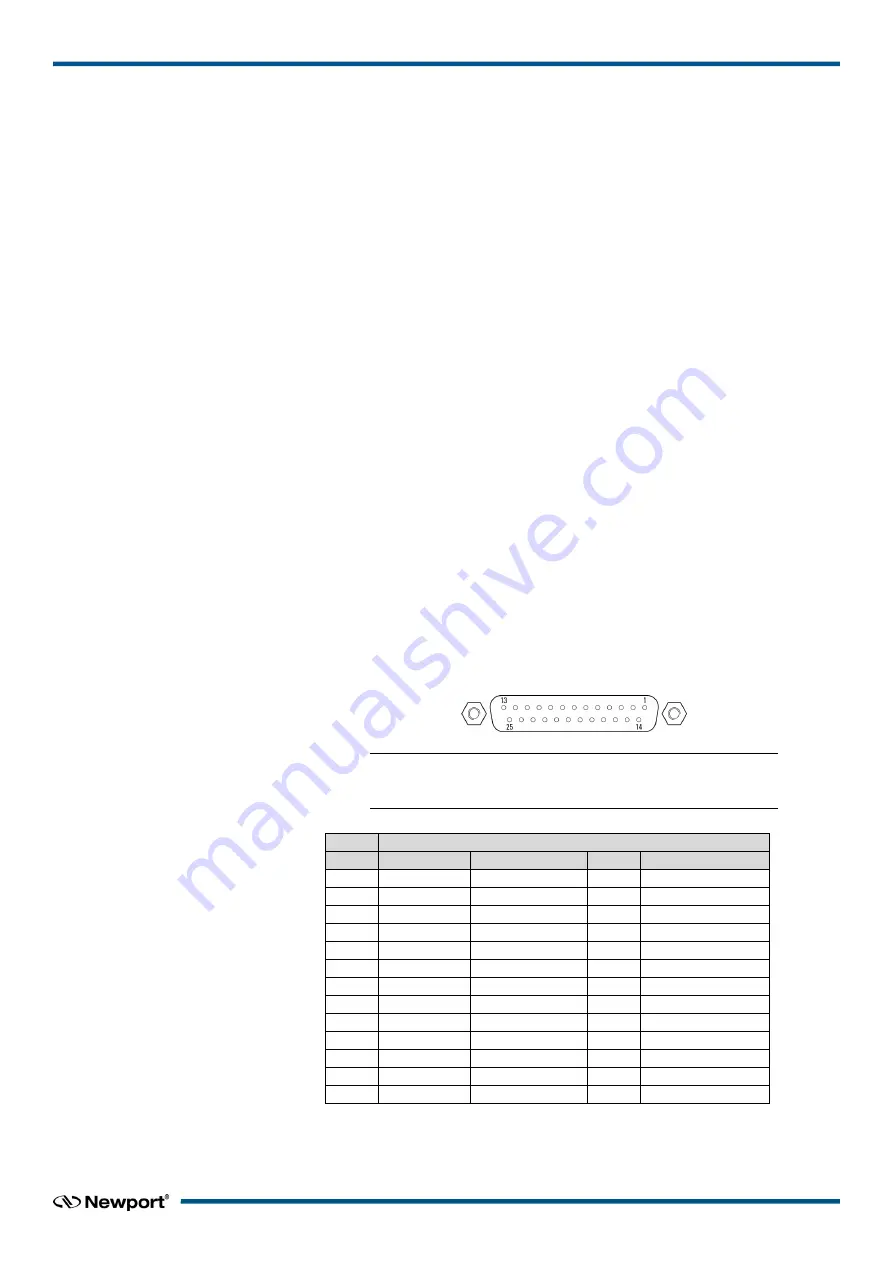
Axis Connectors
MOTOR DRIVER 1 TO 3
NOTE
Mating connector: Male SUB-D25 with UNC4/40 lockers.
MOTOR DRIVER
Pin # DC Motor Stepper Motor Pin #
All Motors
1
N.C.
+ Phase 1
13
Origin
2
N.C.
+ Phase 1
14
GND
3
N.C.
- Phase 1
15
Index
4
N.C.
- Phase 1
16
GND
5
Motor+
+ Phase 2
17
+ Travel Limit
6
Motor+
+ Phase 2
18
- Travel Limit
7
Motor-
- Phase 2
19
Encoder A
8
Motor-
- Phase 2
20
Encoder B
9
N.C.
N.C.
21
+5V
10
N.C.
N.C.
22
GND
11
N.C.
N.C.
23
Encoder /A
12
N.C.
N.C.
24
Encoder /B
25
/Index
Figure 18: Motor driver connectors.


