


- 36 -
www.NewLeader.com
(800) 363-1771
307074-AA-I
L4000G4
NOTE:
Visit www�newleadervip�com and enter parameters to determine minimum and maximum
application rates and feedgate openings for optimal performance of your spreader�
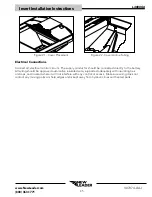
Feedgate Adjustment
Stay out of the spreader� If it’s necessary to enter the spreader, return to the shop,
empty body, turn off all power, set vehicle brakes, lock engine starting switch and
remove keys before entering� Tag all controls to prohibit operation� Tags should be
placed, and later removed, only by person working in the body�
Adjust the insert’s front feedgate prior to installation�
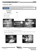
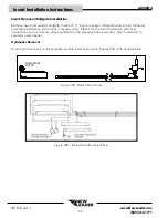
Figure 2A - 1 1/2” (3�81 cm) or 2” (5�08 cm) Opening
(Style I
M
ult
A
pplier
)
Figure 2B - 3” (7�62 cm) Opening
(Style I
M
ult
A
pplier
)
Style I MultApplier - To adjust main bin’s feedgate opening on a Style I MultApplier-equipped unit:
position front feedgates on MultApplier as necessary to achieve a 1-1/2 inch (3�81 cm), 2 inch (5�08 cm)
(Figure 2A) or 3 inch (7�62 cm) (Figure 2B) opening� Position both feedgates with short side down for a
3” (7�62 cm) opening� NOTE: Both feedgates are installed for shipping�
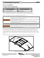
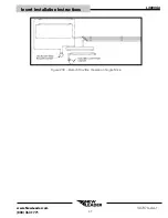
Figure 3A - 2 1/2” (3�81 cm) or 2” (5�08 cm) Opening
(Style II
M
ult
A
pplier
/M
ulti
B
in
)
Figure 3B - 4” (10�16 cm) Opening
(Style II
M
ult
A
pplier
/M
ulti
B
in
)
Style II MultApplier/MultiBin - To adjust main bin’s feedgate opening on a Style II MultApplier or
MultiBin-equipped unit: position front feedgate on insert as necessary to achieve a 1 1/2 inch (3�81 cm)
(Figure 3A) to 4 inch (10�16 cm) (Figure 3B) opening in 1/2 inch increments�
Insert Installation Instructions


