2-55
87519804 NA
Issued 11-06
Bur
CHAPTER 2 - 667TA ENGINE OVERHAUL
ENGINE REPAIR MANUAL
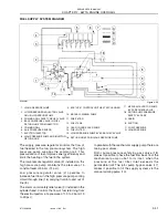
LOCATION OF THE MAIN ELECTRICAL COMPONENTS
BS06K072
Figure 2-71
T h e e n g i n e i s c o n t r o l l e d by t h e E D C 7 U C 3 1
electronic control module. The control module is
installed on flexible mounts to reduce vibration
transmitted by the engine. The fuel heat exchanger
removes heat from the controller due to the high
voltages needed for firing the injectors. It removes
the heat from the controller and loses it in the fuel
cooler. It also picks up some engine heat when it is
returned from the cylinder head. The unit is supplied
with a 20 amp fuse. The main relay used to supply
the power to the system is located inside the control
unit.
Through the engine control module, it is possible to
verify the correct operations of the engine and also
h e l p t r o uble s h o o t p ro bl e m s w i t h e rr o r c o d e s
generated from the EDC7UC31 control module.
1. COOLANT TEMPERATURE SENSOR
7. SOLENOID VALVE FOR PRESSURE REGULATOR
2. ELECTRO-INJECTOR
8. FUEL TEMPERATURE SENSOR
3. FUEL RAIL PRESSURE SENSOR
9. EDC7UC31 ELECTRONIC CONTROL UNIT
4. BOOST TEMPERATURE/PRESSURE SENSOR
10. CRANKSHAFT SENSOR
5. STARTER MOTOR
11. ENGINE OIL PRESSURE/TEMPERATURE SENSOR
6. CAMSHAFT SENSOR
12. HEATING ELEMENT FOR PRE-POST HEATING
2
3
4
10
11
12
1
7
8
9
5
6
Summary of Contents for 667TA/EBF
Page 4: ...SECTION 1 ENGINE REPAIR MANUAL II Issued 11 06 Bur 87519804 NA NOTES ...
Page 8: ...1 2 Issued 11 06 Bur 87519804 NA CHAPTER 1 DIAGNOSTICS ENGINE REPAIR MANUAL NOTES ...
Page 16: ...1 10 Issued 11 06 Bur 87519804 NA CHAPTER 1 DIAGNOSTICS ENGINE REPAIR MANUAL NOTES ...
Page 22: ...2 4 Issued 11 06 Bur 87519804 NA CHAPTER 2 667TA ENGINE OVERHAUL ENGINE REPAIR MANUAL NOTES ...
Page 144: ...3 2 Issued 11 06 Bur 87519804 NA CHAPTER 3 CHARGING AND START UP ENGINE REPAIR MANUAL NOTES ...
Page 150: ...3 8 Issued 11 06 Bur 87519804 NA CHAPTER 3 CHARGING AND START UP ENGINE REPAIR MANUAL NOTES ...


