background image

2-86

Issued 11-06

Bur

87519804 NA

CHAPTER 2 - 667TA ENGINE OVERHAUL

 ENGINE REPAIR MANUAL

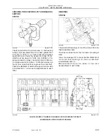
INSTALLING THE TAPPETS AND CAMSHAFT

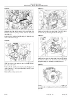
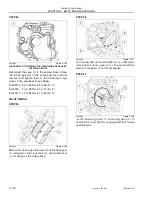
STEP 53

BS06K274

Figure 2-147

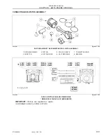
Lubricate tappets (1) and install them into their
respective seats of the engine block.

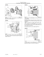
STEP 54

BS06K275

Figure 2-148

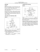
lubricate the camshaft support bearings and install
camshaft (1) taking care not to damage the bearings
or support seats.

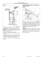
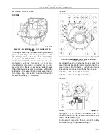
STEP 55

BS06K276

Figure 2-149

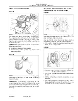
Place camshaft (1), retaining plate (2) with the slotted
hole facing the engine block upper side and the
stamping facing the operator, then tighten bolts to the
specified torque 20 to 30 Nm (14.8 to 22.1 lb.-ft.).

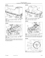
STEP 56

BS06K277

Figure 2-150

Check the camshaft end play (1). It must be between
0.13 - 0.23 mm (0.005 - 0.009 in.).

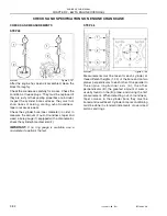
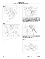
STEP 57

BS06K278

Figure 2-151

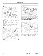
Install nozzles (2) and tighten fastening bolts (1)
using general bolt torque specifications.

1

1

1

2

1

1

2

Summary of Contents for 667TA/EBF

Page 1: ...PAIR MANUAL 667TA EEG 667TA EEC 667TA EBF 667TA EED 667TA EBJ 667TA EDJ Issued 11 2006 Book Form Number 87519804 NA Copyright 2006 CNH America LLC All Rights Reserved Printed in U S A Bur Source Code No unknown ...

Page 2: ...ta given in this publication is subject to production variations Dimensions and weights are only approximate Illustrations do not necessarily show products in standard condition For exact information about any particular product please consult your Dealer Revision History Issue Issue Date Applicable Machine Remarks First Edition 11 2006 667TA EEG 667TA EEC 667TA EBF 667TA EED 667TA EBJ 667TA EDJ 8...

Page 3: ...ST GAS RECIRCULATION SYSTEM 2 22 ENGINE LUBRICATION 2 30 ENGINE COOLING 2 35 HIGH PRESSURE ELECTRONIC INJECTION SYSTEM COMMON RAIL 2 37 EDC7UC31 ELECTRONIC CONTROL UNIT OPERATION 2 38 FUEL SUPPLY SYSTEM 2 40 COMMON RAIL 2 50 COMMON RAIL PRESSURE RELIEF VALVE 2 51 ELECTRO INJECTOR 2 52 LOCATION OF THE MAIN ELECTRICAL COMPONENTS 2 55 CHECKING THE FUEL SYSTEM 2 67 ENGINE OVERHAUL ON THE BENCH 2 72 CH...

Page 4: ...SECTION 1 ENGINE REPAIR MANUAL II Issued 11 06 Bur 87519804 NA NOTES ...

Page 5: ...CHAPTER 1 ENGINE REPAIR MANUAL DIAGNOSTICS Issued 11 2006 Book Form Number 87519804 NA Copyright 2006 CNH America LLC All Rights Reserved Printed in U S A Bur Source Code No unknown 667TA TIER III ...

Page 6: ...nits previously sold All data given in this publication is subject to production variations Dimensions and weights are only approximate Illustrations do not necessarily show products in standard condition For exact information about any particular product please consult your Dealer Revision History Issue Issue Date Applicable Machines Remarks First Edition 11 2006 667TA EEG 667TA EEC 667TA EBF 667...

Page 7: ...on t Start 1 4 Engine Overheats 1 5 Engine Lacks Power And Runs Erratically 1 6 Engine Exhaust Smoke Black Or Dark Grey 1 7 Engine Exhaust Smoke Grey Verging On White 1 7 Engine Exhaust Smoke Light Blue 1 7 Engine Knocks Irregularly 1 8 Engine Stops 1 9 Excessive Or Insufficient Oil Pressure 1 9 Excessive Fuel Consumption 1 9 87519804 NA ...

Page 8: ...1 2 Issued 11 06 Bur 87519804 NA CHAPTER 1 DIAGNOSTICS ENGINE REPAIR MANUAL NOTES ...

Page 9: ... Figure 1 1 The EST system allows diagnoses on machines by detecting the operating parameters of electronic control components control units sensors etc and check flow rates pressures and temperatures It is also capable of reading fault codes on the engine To help with troubleshooting the engine failure mode ...

Page 10: ...heck using a multi meter replace or repair Yes Fuel filters plugged Yes Replace No The fuel system or injection pump shows signs of air in system Yes Check and repair air leaks No The fuel system shows traces of water Yes Check and clean the fuel system including the fuel tank No High pressure pump working properly No Check using Electronic Service Tool EST and repair or replace if necessary Yes I...

Page 11: ... overhaul or replace Yes Thermostat working properly No Replace Yes Radiator plugged or leaking Yes Wash down repair leaks and flush out radiator If necessary replace radiator No Oil in radiator fluid Yes Replace oil cooler No Air to Air Cooler and hoses leaking Yes Clean or replace faulty parts No Openings for coolant flow within the cylinder head and engine block plugged Yes Clean thoroughly No ...

Page 12: ... tank No Thermostat working properly No Replace Yes High pressure pump working properly No Check using the Electronic Service Tool EST and repair or replace if necessary Yes Injectors working properly No Check using the Electronic Service Tool EST and repair or replace if necessary Yes High pressure fuel side leaking Yes Check for leaks around O rings and gaskets No Turbocharger working properly N...

Page 13: ...rs on defective parts valves piston rings etc Injectors working properly No Check using the Electronic Service Tool EST and repair or replace if necessary Yes Coolant level correct No Possible flow of coolant into the combustion chamber replace the cylinder head gasket or overhaul the engine Yes Pre Post heating system working properly No Check using a multi meter replace or repair Yes Fresh clean...

Page 14: ...ollowing items Play between the pistons and the cylinder liners integrity of piston rings play between the pins and the piston hubs Replace the defective parts or overhaul the engine No Knock detected in the cylinder head Yes Check the following items Play between the rocker arms and the valves injection pump timing valve timing Adjust to proper specification No Knock detected in valve gear Yes Ch...

Page 15: ... control valve working properly No Check and replace if necessary Yes Proper engine oil SAE viscosity No Replace engine oil with proper viscosity oil Yes Oil pump delivering proper pressure No Check and replace if necessary Yes Main bearings and connecting rod bearings in acceptable condition No Replace the bearings and reface if necessary the crankshaft Fuel tank and lines leaking Yes Repair leak...

Page 16: ...1 10 Issued 11 06 Bur 87519804 NA CHAPTER 1 DIAGNOSTICS ENGINE REPAIR MANUAL NOTES ...

Page 17: ...APTER 2 ENGINE REPAIR MANUAL 667TA ENGINE OVERHAUL Issued 11 2006 Book Form Number 87519804 NA Copyright 2006 CNH America LLC All Rights Reserved Printed in U S A Bur Source Code No unknown 667TA TIER III ...

Page 18: ... on units previously sold All data given in this publication is subject to production variations Dimensions and weights are only approximate Illustrations do not necessarily show products in standard condition For exact information about any particular product please consult your Dealer Revision History Issue Issue Date Applicable Machines Remarks First Edition 11 2006 667TA EEG 667TA EEC 667TA EB...

Page 19: ...ED 2 24 Cylinder Head Engines 667TA EEG 667TA EEC 2 25 Cylinder Head Engine 667TA EDJ 2 26 Valves and Valve Seats 2 27 Valve Bridges 2 27 Engine Head Machining 2 28 Engine Flywheel 2 28 Accessory Equipment Drive 2 29 ENGINE LUBRICATION 2 30 Oil Cooler 2 31 Oil Pressure Control Valve 2 31 By pass Valve 2 31 Oil Pump 2 32 Oil Pan Sump Engines 667TA EEG 667TA EEC 667TA EBF 667TA EED 667TA EDJ 2 32 Oi...

Page 20: ...IN ELECTRICAL COMPONENTS 2 55 EDC7UC31 Electronic Control Unit 2 56 Cabling Connector Pinout On Engine 2 57 Connector A Injectors Pinout Diagram 2 58 Connector C Sensors Pinout Diagram 2 58 Crankshaft Sensor 2 59 Camshaft Sensor 2 59 Boost Temperature Pressure Sensor 2 60 Engine Oil Temperature Pressure Sensor 2 60 Common Rail Fuel Pressure Sensor 2 61 Electro injectors 2 62 Intake Air Pre Post Re...

Page 21: ... 96 Installing the Piston Rings 2 97 Installing the Connecting Rod Piston Assemblies In the Cylinder Bores 2 97 Measuring Crank Pin Assembly Play 2 98 Checking Piston Protrusion 2 99 Timing Gear Case 2 99 Valve Timing 2 100 Flywheel Cover Case 2 101 ENGINE FLYWHEEL 2 102 Replacing Engine Flywheel Ring Gear 2 102 CYLINDER HEAD 2 107 Removing the Valves 2 107 Checking Cylinder Head Water Seal 2 108 ...

Page 22: ...2 4 Issued 11 06 Bur 87519804 NA CHAPTER 2 667TA ENGINE OVERHAUL ENGINE REPAIR MANUAL NOTES ...

Page 23: ...APTER 2 667TA ENGINE OVERHAUL ENGINE REPAIR MANUAL ENGINES BS06K010 Figure 2 1 ENGINES 667TA EEG 667TA EEC BS06K012 Figure 2 2 ENGINES 667TA EED 667TAEBD BS06K011 Figure 2 3 ENGINES 667TA EED 667TAEBF BS06K628 Figure 2 4 ENGINE 667TA EDJ ...

Page 24: ...48 kW 198 5 H P B F 157 kW 210 5 H P B D 169kW 226 6 H P Compression Ratio B 16 5 1 130 kW 174 H P D 17 5 1 130 kW 174 H P E 17 5 1 130kW 174 H P E Electronic Injection Common Rail A Intercooled T Turbocharged 67 Total Displacement in Liters Cubic Inches 6 7 Liters 409 Cubic Inches 6 Number of Cylinders A 667TA 667TA 667TA 667TA 667TA 667TA B EEG EEC EBF EED EBD EDJ C 6 CYLINDERS D 6728 cm 410 6 c...

Page 25: ...imum power rating net power at flywheel ISO 14396 137 kW 148 kW 157 kW 145 kW 169 kW 97 kW 2100 rpm 2100 rpm 2000 rpm 2000 rpm 2000 rpm 2200 rpm 184 hp 198 hp 211 hp 194 hp 227 hp 130 hp 2100 rpm 2100 rpm 2000 rpm 2000 rpm 2000 rpm 2200 rpm 8 Maximum Torque 710 Nm 810 Nm 952 Nm 860 NM 1002 Nm 607 Nm 1400 rpm 1400 rpm 1400 rpm 1400 rpm 1400 rpm 1400 rpm 524 pound feet 597 pound feet 702 pound feet ...

Page 26: ...e 79 to 83 C 174 to 181 F 83 to98 C 181 to 208 F 14 Oil capacity 1st filling No Information Available No Information Available Oil capacity engine sump No Information Available No Information Available Oil capacity engine sump filter 17 litres 18 qt 19 litres 20 qt 15 Feeding Bosch type injection High pressure Common Rail 16 Pump setting No Information Available 17 Start of delivery No Information...

Page 27: ... in 5 Protrusion of pistons from crankcase No Information Available 6 Piston pin Ø3 37 994 to 38 000 mm 1 4958 to 1 4961 in 7 Piston pin Pin seat 0 01 to 0 022 mm 0 0004 to 0 0009 in 8 Piston ring grooves measured on Ø of 101 mm 3 976366 in X1 2 705 to 2 735 mm 0 1065 to 0 1077 in X2 2 420 to 2 440 mm 0 0953 to 0 0961 in X3 4 03 to 4 05 mm 0 1587 to 0 1594 in Piston rings measured 1 5 mm 0 0590549...

Page 28: ...252 to 1 6359 in Inner Ø3 38 019 to 38 033 mm 1 4968 to 1 4974 in 14 Connecting rod small end bearing seat 0 266 to 0 566 mm 0 0105 to 0 0223 in 15 Piston pin bearing 0 019 to 0 039 mm 0 0007 to 0 0015 in 16 Measurement dimension No Information Available Maximum error on connecting rod axis parallelism No Information Available Journals Ø1 82 990 to 83 010 mm 3 2673 to 3 2681 in Crank pins Ø2 68 98...

Page 29: ...16 to 0 0041 in Half bearing crank pins 0 039 to 0 111 mm 0 0015 to 0 0044 in 19 Main half bearings Connecting rod half bearings 0 250 mm 0 0098 in 0 500 mm 0 0197 in 20 Main journal of thrust bearing X1 37 475 to 37 545 mm 1 4754 to 1 4781 in 21 Main bearing housing of thrust bearing X2 25 980 to 26 480 mm 1 0228 to 1 0425 in 22 Shoulder half ring X3 37 280 to 37 380 mm 1 4677 to 1 4716 in 23 Cra...

Page 30: ... in 4 seat on head for valve seat Intake 34 837 to 34 863 mm 1 3715 to 1 3725 in seat on head for valve seat Exhaust 34 837 to 34 863 mm 1 3715 to 1 3726 in 5 Valve seat outer diameter angle of valve seats on cylinder head Intake Ø2 34 917 to 34 931 mm 1 3747 to 1 3752 in angle 60 Exhaust Ø2 34 917 to 34 931 mm 1 374681 to 1 375232 in angle 45 6 Recessing Intake valve 0 590 to 1 110 mm 0 0232 to 0...

Page 31: ... camshaft with a load of 3 3 kNm 741 8695 lbf Ø 59 222 to 59 248 mm 2 3316 to 2 3326 in 13 Camshaft bearing inner diameter Ø 54 083 to 54 147 mm 2 1292 to 2 1318 in 14 Bearing and seats in crankcase 0 113 to 0 165 mm 0 0044 to 0 0065 in 15 Bearing and main journals 0 038 to 0 162 mm 0 0015 to 0 0064 in 16 Useful cam lift Intake 6 045 mm 0 2380 in Useful cam lift Exhaust 7 239 mm 0 2850 in 17 Tappe...

Page 32: ... 20 7 lb ft Rocker arm support fastening bolts 31 to 41Nm 22 9 to 30 2 lb ft Nut for rocker arm adjusting bolt 20 to 28 Nm 14 8 to 20 7 lb ft Bolts fastening the pulley on the crankshaft 1st phase 45 to 55 Nm 33 2 to 40 6 lb ft 2nd phase additional rotation 90 5 degrees Cam shaft shoulder plate fastening bolts 20 to 28 Nm 14 8 to 20 7 lb ft Fan support fastening bolts 20 to 30 Nm 14 8 to 22 1 lb f...

Page 33: ... bolt 44 to 55Nm 32 5 to 40 6 lb ft Camshaft sensor fastening bolt 6 to 10 Nm 4 4 to 7 4 lb ft Crankshaft sensor fastening bolt 6 to 10 Nm 4 4 to 7 4 lb ft Engine coolant temperature sensor fastening bolt 17 to 23 Nm 12 5 to 17 0 lb ft Oil pressure temperature sensor fastening bolt 5 to 7 Nm 3 7 to 5 2 lb ft Fuel pressure sensor fastening bolt 30 to 40 Nm 22 1 to 29 5 lb ft Fuel temperature sensor...

Page 34: ...Rail 380000665 Tool for removing the crankshaft front seal 380000663 Tool for removing the crankshaft rear seal 380000671 Injector extracting tool 380000666 Coupler for installing the crankshaft front seal 380000664 Coupler for installing the crankshaft rear seal except engines 667TA EBF 667TA EED 380000988 Tool for rotating the engine flywheel except engines 667TA EBF 667TA EED 380001099 Tool for...

Page 35: ...E REPAIR MANUAL 667TA ENGINES BS06K020 Figure 2 13 1 TURBOCHARGER 5 WATER PUMP 9 FUEL FILTER 2 AUTOMATIC BELT TENSIONER 6 DAMPER FLYWHEEL 10 HIGH PRESSURE PUMP 3 ALTERNATOR 7 OIL PAN SUMP 11 COMMON RAIL 4 FIXED GUIDE PULLEY 8 ELECTRONIC CONTROL UNIT 5 6 3 2 1 11 9 10 8 7 4 ...

Page 36: ... camshaft bearings 3 for the water oil cooler 7 water pump 2 and oil pump 4 The block also incorporates the water jackets for cooling and the oil galleys for lubrication The crankshaft stiffening plate 6 is installed on the crankshaft main bearing cap bolts into the engine block and ensures greater resistance to mechanical stress 1 CYLINDER BORE 3 SEATS FOR CAMSHAFT BEARINGS AND TAPPETS 5 MAIN BEA...

Page 37: ...e force fitted onto the rear of the crankshaft timing gear 3 and the flywheel mounting hub 4 The main bearing shells are made of steel with a antifriction alloy plating One of the main bearing shells is equipped with shoulders to limit crankshaft endplay The timing drive gear 3 and the flywheel attachment hub 4 are installed on the rear of the crankshaft with a force fit and cannot be replaced CRA...

Page 38: ...ined by means of the innovative fracture splitting system rather than the conventional machining process The connecting rod crankshaft bearing shells are made of steel plated with an antifriction alloy Each connecting rod is marked By a number on the connecting rod body and on the cap indicating the match and the cylinder in which they are assembled By a letter on the connecting rod body indicatin...

Page 39: ...erent functions and different geometry 1st piston ring with trapezoidal keystone section ceramic chrome plating 2nd piston ring with torsional conical rectangular section 3rd piston ring with double oil ring wiper with internal spring The following reference data is engraved into the piston crown 1 Spare part number and design modification number 2 Stamping facing the crankcase front side indicati...

Page 40: ...rculation system EGR lowers the combustion temperature by decreasing the concentration of oxygen in the combustion chamber Creating an effective system to control the emission of NOx The internal EGR system exhaust cam design permits some of the exhaust gases to be returned back into the engine cylinders This type of EGR internal EGR is not provided with any electronically controlled element The s...

Page 41: ...67TA ENGINE OVERHAUL ENGINE REPAIR MANUAL VALVE CONTROL BS06K027 Figure 2 20 1 ROCKER ARM 3 PUSH ROD 5 SPRING SEAT 7 CAMSHAFT 9 VALVE BRIDGE 2 ADJUSTER SCREW 4 VALVE SPRING RETAINER KEEPERS 6 SPRING 8 TAPPET 10 ROCKER SPINDLE 8 7 1 4 2 3 5 6 9 10 ...

Page 42: ...67TA EBD 667TA EED The cast iron cylinder head is machined to accommodate the following parts Valve seats 4 Injectors 2 Thermostat 3 The cylinder head is also fitted for the following components to be installed on to the cylinder head Exhaust manifold 1 Intake manifold 6 with seat for grid heater 5 1 EXHAUST MANIFOLD 3 THERMOSTAT 5 GRID HEATER 2 INJECTOR 4 VALVE SEAT 6 INTAKE MANIFOLD 6 5 4 3 2 1 ...

Page 43: ...ad is machined to accommodate the following parts valve seats 4 injectors 2 thermostat 3 The cylinder head is also fitted for the following components to be inserted on to the head exhaust manifold 1 intake manifold 7 with seat for grid heater 6 1 EXHAUST MANIFOLD 3 THERMOSTAT 5 SUPPORT WITH WIRING HARNESS 7 INTAKE MANIFOLD 2 INJECTOR 4 VALVE SEAT 6 GRID HEATER 7 5 4 3 2 1 6 ...

Page 44: ...machined to accommodate the following parts valve seats 4 injectors 2 thermostat 3 The cylinder head is also fitted for the following components to be inserted on to the head exhaust manifold 1 intake manifold 7 with seat for grid heater 6 1 EXHAUST MANIFOLD 3 THERMOSTAT 5 SUPPORT WITH WIRING HARNESS 7 INTAKE MANIFOLD 2 INJECTOR 4 VALVE SEAT 6 GRID HEATER 7 6 5 4 3 2 1 ...

Page 45: ...igure 2 25 Oil seals 1 installed on the valve stems BS06K032 Figure 2 26 1 7 042 TO 7 062MM 0 277 TO 0 278 IN 2 INTAKE VALVES 3 EXHAUST VALVES The cylinder head does not have guide inserts The valve guide is machined directly into the head casting VALVE BRIDGES BS06K033 Figure 2 27 1 JUMPER 2 RODS NOTE When installing the cylinder head the orientation of valve bridges must be positioned with marks...

Page 46: ...ed 0 13mm 0 0051 in ENGINE FLYWHEEL The flywheel 1 is not timed to the crankshaft and does not have any stamping notch or reference hole for sensors or timing Equal position of fastening bolt holes 2 allows it to be installed in any position BS06K035 Figure 2 29 ENGINES 667TA EEG 667TA EEC BS06K037 Figure 2 30 ENGINES 667TA EED 667TA EBD BS06K036 Figure 2 31 ENGINES 667TA EBF 667TAEED BS06K629 Fig...

Page 47: ... EQUIPMENT DRIVE BS06K038 Figure 2 33 A Poly V belt 3 transmits the rotation of the crankshaft 5 to water pump 4 and to the alternator 2 The tension of the belt is controlled by the automatic belt tensioner 1 5 3 4 2 1 1 AUTOMATIC BELT TENSIONER 2 ALTERNATOR 3 POLY V BELT 4 WATER PUMP 5 CRANKSHAFT ...

Page 48: ...ur tooth gear force fitted on the crankshaft water oil cooler 4 housed in the engine block under the oil filter support by pass valve 2 for clogged oil filter cut off cartridge type oil filter 3 1 TURBO OIL PRESSURE CONTROL VALVE 3 CARTRIDGE TYPE OIL FILTER 5 OIL PUMP 2 BY PASS VALVE 4 OIL WATER COOLER A OIL PAN 667TA EED 667TA EBD C PRESSURIZED OIL PATH B OIL PAN 667TA EEG 667TA EEC 667TA EBF 667...

Page 49: ...um pressure 1 2 bar 17 4 psi maximum pressure 3 8 bar 55 1 psi BY PASS VALVE BS06K042 Figure 2 37 A DIRECTION OF FLOW Blow by max 20cm min 68oz min with 0 83 bar 12 psi pressure at 26 7 C 80 F oil temperature 1 HEAT EXCHANGER BODY 3 WATER OIL COOLER 5 OIL RETURN TO FILTER 7 OIL FILTER 2 INNER GASKET 4 GASKET BETWEEN COOLER AND ENGINE BLOCK 6 OIL FLOW FROM FILTER 7 6 5 4 3 2 1 1 66MM 2 589 IN 2 41 ...

Page 50: ...EG 667TA EEC 667TA EBF 667TA EED 667TA EDJ BS06K045 Figure 2 40 OIL PAN GASKET INSTALLATION BS06K046 Figure 2 41 STEEL OIL PAN SUMP CROSS SECTIONAL VIEW OF OIL PAN GASKET The steel oil pan sump 1 is secured to the engine block by an aluminium plate 3 and a rubber gasket 2 See figure 2 41 The C section rubber gasket 2 installed on the edge of the oil pan enhances sealing properties and also reduces...

Page 51: ...2 667TA ENGINE OVERHAUL ENGINE REPAIR MANUAL OIL PAN SUMP ENGINES 667TA EED 667TA EBD BS06K047 Figure 2 42 CAST IRON OIL PAN SUMP The cast iron oil pan sump is fastened to the engine block by bolts with interposed flat washers and a thin gasket ...

Page 52: ...by oil vapor while condensing them partially Condensed oil returns to the oil pan sump while residual vapors are collected and routed through the blow by filter 3 In blow by filter 3 a portion of the vapors partially condense and return to the oil pan sump through line 4 while the remaining is recirculated to the engine intake by line 2 1 PRE SEPARATOR 3 BLOW BY FILTER A OIL CONDENSATE 2 RECIRCULA...

Page 53: ... circulation type and is made up of the following components Oil cooler used to cool the lubricating oil see oil cooler page 2 31 Centrifugal water pump housed in the front of the engine block Thermostat used to regulate coolant flow 1 OIL COOLER 3 THERMOSTAT B WATER RECIRCULATING IN ENGINE 2 WATER PUMP A WATER FROM THERMOSTAT OUTLET C WATER TO PUMP INLET 2 1 C B A 3 ...

Page 54: ...ump is housed in a cavity in the front of the engine block and is driven by a Poly V belt The water pump is sealed to the block by a rubber ring The engine temperature is controlled by a thermostat BS06K052 Figure 2 47 THERMOSTAT A STROKE STARTS AT 96 C 204 F 7 5MM 30 IN Thermostat opening for engines 667TA EEG EEC EBF EED EBD 79 to 83 C 174 to 181 F 667TA EDJ 83 to 98 C 181 to 208 F A ...

Page 55: ...stem serves to optimize operation of the engine while limiting emissions and fuel consumption For engines more powerful than 152 kW 203 hp the CRIN2 injectors have DLLA nozzles that work up to a pressure of 1600 bar 23206 psi while engines less powerful than 152 kW 203 hp are fitted with DSLA nozzles which work with pressures up to 1450 bar 21030 psi 1 HARNESS TO INJECTORS 5 CRANKSHAFT SENSOR 9 CA...

Page 56: ...perature returns below 100 C 212 F the engine resumes normal operation In some applications the intake manifold temperature is the reference temperature MAXIMUM ENGINE SPEED LIMITING Depending on the application the control unit memory can contain appropriate engine speed limits When the engine speed surpasses these limits the control unit activates power reduction by controlling turn on time of t...

Page 57: ...ing the number of revs in order to improve interpretation of the signals Power restrictions as operating temperature increases When the temperature of the supercharging air rises above 88 C 190 F power reduction is started when a temperature of 120 C 248 F is reached performance is further reduced and is comparable to that of the same engine if it were aspirated Reduction of power as reference tem...

Page 58: ...the corresponding cylinder The fuel system is composed of a low pressure circuit and a high pressure circuit The high pressure circuit consists of the following lines Line connecting the high pressure pump outlet to the common rail Lines supplying the electro injectors from the common rail The low pressure circuit is composed of the following lines Fuel line from fuel tank to prefilter Lines suppl...

Page 59: ... parallel with the mechanical supply pump there are two by pass valves Rotor pump pressure safety by pass valve 18 makes it possible to have the fuel flow back from the mechanical pump outlet to its inlet when the pressure at the fuel filter inlet exceeds the permissible limit The rotor pump by pass valve 17 makes it possible to fill the supply system via the manual priming pump 10 1 HIGH PRESSURE...

Page 60: ...less than 0 C 32 F and is heated until the fuel reaches 5 C 41 F Fuel temperature is monitored by the EDC7UC31 control unit 1 FUEL FILTER BRACKET A OUTLET CONNECTION TO HIGH PRESSURE PUMP 2 FUEL HEATER CONNECTOR B COMMON RAIL CYLINDER HEAD INJECTORS DISCHARGE LINE INLET CONNECTION 3 ELECTRIC FUEL HEATER C CONNECTION TO HIGH PRESSURE PUMP DISCHARGE LINE 4 FUEL FILTER D INLET CONNECTION FROM FEED PU...

Page 61: ... feed pump enters port A flows around the outside of the gears and out through port B MECHANICAL SUPPLY PUMP OUTLET OVERPRESSURE CONDITION BS06K058 Figure 2 53 Pressure safety valve 1 opens when pump outlet pressure B is excessive due to filter restriction or charge pressure regulator malfunction The pressure of the fuel would then overcome the force exerted by spring 1 allowing fuel to flow to th...

Page 62: ...ve 2 opens when the engine is turned off The supply system has to be filled with the manual priming pump When activating the hand pump the by pass valve 2 is opened due to inlet pressure this allows the fuel flow to outlet B 1 PRESSURE SAFETY VALVE A FUEL INLET FROM TANK 2 PRIMING BY PASS VALVE IN CLOSED POSITION B FUEL OUTLET TO FILTER 2 1 B A ...

Page 63: ...pump is the mechanical gear feed pump which is driven by the high pressure pump shaft IMPORTANT The high pressure pump unit can not be overhauled there are no adjustments 1 FUEL OUTLET CONNECTION TO RAIL 2 HIGH PRESSURE PUMP 3 HIGH PRESSURE REGULATOR 4 FUEL INLET CONNECTION FROM FILTER 5 FUEL DRAIN RETURN CONNECTION TO FILTER BRACKET 6 FUEL INLET CONNECTION FROM CONTROL UNIT HEAT EXCHANGER 7 FUEL ...

Page 64: ...UMP 1 MECHANICAL GEAR CHARGE FEED PUMP 4 INDIVIDUAL HIGH PRESSURE PUMP PLUNGER 1 OF 3 7 HIGH PRESSURE PUMP FUEL INLET FROM FILTER 2 GEAR SET 5 BY PASS VALVES ON FEED PUMP 8 5 BAR 72 PSI LOW PRESSURE FUEL REGULATOR VALVE 3 HIGH PRESSURE FUEL DELIVERY VALVE TO COMMON RAIL 6 PUMP SHAFT 9 HIGH PRESSURE REGULATOR SOLENOID VALVE 9 7 6 4 3 2 1 5 8 ...

Page 65: ...is composed of Three pistons 5 which are actuated by a three lobe element 2 on the pump shaft 6 When the shaft 6 rotates the three lobe element 2 actuates the piston 5 pumping high pressure fuel past the ball delivery valve 4 to the common rail 7 8 2 6 5 1 4 3 1 CYLINDER 5 PISTON 2 THREE LOBE ELEMENT 6 PUMP SHAFT 3 CAP INTAKE VALVE 7 LOW PRESSURE FUEL INLET 4 BALL DELIVERY VALVE 8 PUMPING ELEMENTS...

Page 66: ...nger is determined by pressure regulator 7 The pressure regulator controls high pressure pump outlet flow based on PWM pulse width modulated command received from the EDC7UC31 control unit During the plunger compression phase the fuel reaches sufficient pressure to open the common rail delivery valve 2 and is forced through outlet 1 to the common rail 7 6 5 4 3 2 1 1 OUTLET FOR RAIL DELIVERY LINE ...

Page 67: ...e high pressure pump is metered by the high pressure regulator The high pressure regulator is controlled by the EDC7UC31 control unit through a PWM pulse width modulated signal When fuel is sent to a pumping element the corresponding piston is moving downwards suction stroke When the piston stroke is reversed the intake valve closes and the fuel in the pumping element chamber is compressed into th...

Page 68: ...e line between the fuel filter and high pressure pump is to be removed or replaced be sure that components are absolutely clean COMMON RAIL BS06K066 Figure 2 65 COMMON RAIL The common rail volume is a high pressure fuel storage device It has a small volume to allow a rapid pressurization at startup at slow idle and in case of high flow rates It has enough volume to minimize system spikes caused by...

Page 69: ...haust the fuel and consequently reduce the pressure until reaching the proper pressure Then it reduces the pressure into the common rail to approximately 800 bar 11603 psi The relief valve enables engine operation at limited performance avoiding fuel overheating and safeguarding the system If the dual stage relief valve opening pressure is reached the EDC7UC31 control unit stops operation of the p...

Page 70: ...ol volume 9 fuel flows towards control fuel outlet 12 making a pressure drop occur in control volume 9 Simultaneously the fuel pressure into pressure chamber 8 makes plunger 2 lift causing injection of fuel into the cylinder INJECTION END When coil 4 is de energized shutter ball 6 goes back to its closed position to restore a balance of forces to make plunger 2 go back to its closed position and e...

Page 71: ...ing to power developed by the engine 1 Injectors Jet Engines Pressures Minimal operating pressure Nominal operating pressure CRIN 1 not available 667TA EEG 667TA EEC not available not available CRIN 2 DLLA 137 PV 3 667TA EBF 667TA EBD 250 bar 3626 psi 1600 bar 23206 psi CRIN 2 DSLA 143 PV 3 667TA EED 250 bar 3626 psi 1400 bar 20305 psi CRIN 2 not available 667TA EDJ 250 bar 3626 psi 1400 bar 20305...

Page 72: ... FROM INJECTORS The pressure limiter for the fuel return is housed on the rear of the cylinder head and adjusts the pressure of the fuel returning from injectors at a pressure of 1 3 to 2 0 bars 18 9 to 29 psi By maintaining this pressure to the return fuel the fuel vapor formation inside the injectors is avoided optimizing fuel spraying and combustion A B ...

Page 73: ...en it is returned from the cylinder head The unit is supplied with a 20 amp fuse The main relay used to supply the power to the system is located inside the control unit Through the engine control module it is possible to verify the correct operations of the engine and also help troubleshoot problems with error codes generated from the EDC7UC31 control module 1 COOLANT TEMPERATURE SENSOR 7 SOLENOI...

Page 74: ...ENGINE OVERHAUL ENGINE REPAIR MANUAL EDC7UC31 ELECTRONIC CONTROL UNIT BS06K073 Figure 2 72 EDC7UC31 ELECTRONIC CONTROL UNIT A CONNECTOR TO INJECTORS B CONNECTOR FOR POWER INPUT AND FUNCTIONS PROVIDED FOR IN THE APPLICATION C CONNECTOR TO SENSORS B A C ...

Page 75: ...tic A CONNECTOR A INJECTORS EDC7UC31 ECU POWER 5 CAMSHAFT SENSOR B CONNECTOR B NOT SHOWN SEE NOTE BELOW 6 OIL PRESSURE AND TEMPERATURE SENSOR C CONNECTOR C SENSORS EDC7UC31 ECU SIGNAL 7 FUEL TEMPERATURE 1 INJECTORS FOR CYLINDERS 1 2 8 COOLANT TEMPERATURE SENSOR 2 INJECTORS FOR CYLINDERS 3 4 9 BOOST AIR TEMPERATURE AND PRESSURE SENSOR 3 INJECTORS FOR CYLINDERS 5 6 10 COMMON RAIL PRESSURE SENSOR 4 C...

Page 76: ...t Used 4 Not Used 5 Not Used 6 Not Used 7 Not Used 8 Not Used 9 Camshaft speed sensor Signal 10 Camshaft speed sensor Ground 11 Not Used 12 Common rail temperature and pressure sensor Ground 13 Common rail temperature and pressure sensor Positive 14 Common rail temperature and pressure sensor Signal 15 Coolant temperature sensor Signal 16 Not Used 17 Not Used 18 Fuel temperature sensor Signal 19 C...

Page 77: ... sensor produces signals obtained from magnetic flux field through the openings in a phonic wheel fitted on the crankshaft The crankshaft sensor is connected to the EDC 7 control unit on pins 19C 23C The sensor impedance is approximately 900 ohms CAMSHAFT SENSOR BS06K076 Figure 2 75 A CAMSHAFT SENSOR B CONNECTOR C WIRING DIAGRAM Reference Description EDC7UC31 ECU Camshaft sensor Timing sensor 1 Si...

Page 78: ...sensor and a pressure sensor all in one unit The engine oil temperature pressure sensor is installed on the engine oil filter bracket in a vertical position This sensor measures the engine oil temperature and pressure The sensor is connected to the EDC7UC31 electronic control unit on pins 24C 28C 32C 27C The sensor is supplied with 5 volts The pressure signal is transmitted to the EDC7UC31 electro...

Page 79: ...or measures the internal fuel pressure and feeds back this information to the EDC7UC31 control unit The injection pressure value is used as a pressure control feedback signal and to determine the duration of the electrical pulse for the injection command This sensor is connected to the EDC7UC31 control unit on pins 12C 14C 13C The power supplied to sensor is 5 volts 3 2 1 Reference Description EDC...

Page 80: ... the EDC7UC31 control unit on connector A The impedance of the coil of each injector is 0 56 0 57 ohms Reference Description EDC7UC31 control unit pin CONNECTOR 1 1 Cylinder 2 injector 11A 2 Cylinder 2 injector 6A 3 Cylinder 1 injector 13A 4 Cylinder 1 injector 4A CONNECTOR 2 1 Cylinder 4 injector 14A 2 Cylinder 4 injector 3A 3 Cylinder 3injector 12A 4 Cylinder 3 injector 5A CONNECTOR 3 1 Cylinder...

Page 81: ...red by a relay on the chassis The impedance of the grid plate heater is approximately 0 5 ohms 50 41 BS06K083 Figure 2 82 GRID PLATE HEATER CONTROL RELAY The control relay is connected to the EDC7UC31 control unit B connector The relay is tripped with water and or fuel temperature below 5 C 41 F The relay impedance is approximately 15 ohms WARNING Starting fluids or aids such as ether must not be ...

Page 82: ...stance sensor able to read the coolant temperature in order to provide the EDC7UC31 control unit with an indication of the temperature status of the engine The same signal is utilized by the control unit to drive an instrument panel gauge if present This sensor is connected to the EDC7UC31 control unit on pins 15C 26C The impedance of the coolant temperature sensor at 20 C 68 F is approximately 2 ...

Page 83: ...nit can precisely inject the fuel required The fuel temperature sensor is connected to the EDC7UC31 control unit on pins 35C 18C The sensor impedance at 20 C 68 F is approximately 2 5 k 2500 ohms BS06K211 Figure 2 85 FILTER HEATER RELAY The EDC7UC31 control unit activates the filter heater relay when fuel temp drops below 5 C 41 F 1 2 Reference Description EDC7UC31 Control unit Pin Coolant Fuel 1 ...

Page 84: ...sure regulator solenoid valve The high pressure regulator is controlled by the EDC7UC31 control unit Delivery pressure to the common rail is modulated between 250 and 1600 bar 3626 and 23206 psi by the EDC7UC31 control unit by controlling the high pressure regulator solenoid valve This component is a Normally Open solenoid valve The solenoid is connected to the EDC7UC31 control unit on pins 9A 10A...

Page 85: ...IFIC TEST BS06K215 Figure 2 88 1 FUEL TANK 6 HIGH PRESSURE PUMP 11 M1 PRESSURE GAUGE 0 15 BAR FUEL FILTER INLET 2 PREFILTER 7 HIGH PRESSURE CIRCUIT 12 M2 PRESSURE GAUGE FUEL FILTER OUTLET 3 LOW PRESSURE PUMP 8 COMMON RAIL 13 EXTERNAL CONTAINER PLACED 1M 39 IN BELOW ENGINE 4 FUEL DELIVERY CIRCUIT 9 FUEL RECIRCULATION 5 FUEL FILTER 10 INJECTORS 13 4 1 3 2 4 11 4 4 4 5 10 7 6 9 8 12 9 9 6 13 5 11 12 ...

Page 86: ...nal fuel supply placed 1m 39 in below the engine The engine must start within 20 seconds of activation of the starter motor If the pump is not able to draw fuel to the engine and start the engine the low pressure pump is probably defective After starting the engine check the pressure at 1500 rpm On pressure gauge M1 11 it must be between 6 and 9 bar 87 and 130 psi If lower than 6 bar 87 psi replac...

Page 87: ...c system signals a fault code Engine backfill valve control it means that the EDC7UC31 control unit has recognized that the value has opened after a significant change in the pressure of the rail greater than 1700 bar 24656 psi Since its opening is to be considered a consequence of abnormal increase in pressure the valve is NOT defective even though a great amount of diesel flows out If the valve ...

Page 88: ... in turn is converted into microseconds of injector opening according to the rail pressure NOTE The injectors may have problems of both a mechanical and a electrical nature Therefore before proceeding with the following analysis it is wise to rule out the presence of water in the tank and the fuel prefilter BS06K219 Figure 2 92 1 INJECTOR DUCT LOCKING NUT When the EDC7UC31 control unit warning lig...

Page 89: ...d needles Problem of internal leakage of the injector To identify the defective injector follow the method as described below Measure the quantity of fuel flowing out in one minute from the coupling on the cylinder head If recirculation exceeds 80 ml 2 7 oz per minute plug the rail outlet of one injector 4 at a time using the rail plugs in the test set The defective injector is the one when plugge...

Page 90: ...TANT Push clamp 1 as shown in figure B to disconnect the low pressure fuel lines 2 3 4 from the corresponding connections After disconnecting the line reset the clamp 1 in locking position figure A to prevent distortion to the clamp STEP 4 BS06K223 Figure 2 96 Disconnect fuel line 1 from common rail and from high pressure pump 5 and remove it by taking out securing bolts 2 IMPORTANT When loosing f...

Page 91: ...High pressure regulator 10 EDC7UC31 control unit 11 STEP 7 BS06K226 Figure 2 99 Disconnect from the common rail 2 Fuel line 4 according to procedure on step 3 page 2 72 Fuel lines 5 Injector manifolds 3 Remove the bolts 1 and disconnect the common rail 2 1 INJECTOR CONNECTIONS 5 CRANKSHAFT SPEED SENSOR 9 FUEL HEATER TEMPERATURE SENSOR 2 ENGINE COOLANT TEMPERATURE SENSOR 6 INJECTOR 10 HIGH PRESSURE...

Page 92: ...ring housing 2 complete with gasket Remove bolts 5 and detach the boost temperature pressure sensor 6 Remove nuts 3 and remove the fuel inlet connectors 4 IMPORTANT Disassembled fuel inlet connectors 4 must not be used again They must be replaced with new ones STEP 10 BS06K229 Figure 2 102 Loosen tappet adjusting nuts 1 and unscrew the adjusters Remove the bolts 2 remove the rocker assembly 3 cons...

Page 93: ...ring bolts 1 and remove exhaust manifold in two sections 2 and 3 with related gaskets STEP 14 BS06K233 Figure 2 106 Remove bolts 1 and disconnect intake manifold and heater air shroud 2 Remove the bolts 4 and take off the thermostat housing 3 and the thermostat under the housing Remove the cylinder head 6 fastening bolts 5 STEP 15 BS06K234 Figure 2 107 Attach brackets 1 to cylinder head and remove...

Page 94: ...temperature pressure sensor 2 Take out bolts and then remove heat exchanger oil filter bracket 1 and intermediate plate 4 and relevant gaskets Remove the oil level sensor 3 STEP 19 BS06K238 Figure 2 111 Remove the bolts and disconnect the EDC7UC31 control unit 1 including the heat exchanger STEP 20 BS06K239 Figure 2 112 Remove the nut and disconnect the timing sensor 1 Remove the nuts and disconne...

Page 95: ... 2 116 Place Special Tool 380000665 4 to the front of the crankshaft 2 Working through the guide holes of Special Tool 380000665 4 drill into the internal seal ring 1 with a 3 5mm 9 64 in drill bit A to a depth of 5mm 3 16 in B Secure Special Tool 3800000665 4 to the ring 1 by screwing down the six bolts supplied with tool to the crankshaft front cover Now extract seal ring 1 by tightening bolt 3 ...

Page 96: ...9 Remove bolts and take off gear oil pump 1 IMPORTANT Oil pump 1 can not be repaired STEP 28 BS06K247ID Figure 2 120 Remove tool 1 remove bolts securing flywheel 3 to crankshaft 2 STEP 29 BS06K248 Figure 2 121 Screw two pins 2 of adequate length into the crankshaft holes 3 Remove the flywheel 1 with a hoist STEP 30 BS06K249 Figure 2 122 Remove bolts and take off rear cover 1 IMPORTANT Note the ins...

Page 97: ... EEC EBF EED EDJ Remove the bolts 1 and 4 and remove the oil suction tube 5 Remove the bolts 2 and remove the stiffening plate 3 STEP 33 BS06K252 Figure 2 125 NOTE Only on engines 667TA EED EBD Remove bolts and oil pan sump 1 STEP 34 BS06K253 Figure 2 126 NOTE Only on engines 667TA EED EBD Remove bolts 1 and 4 and remove oil suction tube 5 Remove bolts 2 and remove stiffening plate 3 STEP 35 BS06K...

Page 98: ...MPORTANT Half bearings must be kept in their respective housings If they have to be reused they must be installed in the same position they had prior to being removed STEP 38 BS06K257 Figure 2 130 Remove bolts 1 and take off the main bearing journals 2 STEP 39 BS06K258 Figure 2 131 The main bearing journal cap 1 and its respective thrush bearing 2 have a shoulder to control crankshaft endplay IMPO...

Page 99: ...s 3 IMPORTANT Take note of the mounting position of the main bearings and thrush bearings If they have to be reused again they must be installed in the same position they had prior to being removed STEP 42 BS06K261 Figure 2 134 Remove bolts and take off camshaft 2 retaining plate 1 IMPORTANT Note plate 1 mounting position STEP 43 BS06K262 Figure 2 135 Carefully remove camshaft 1 from engine crankc...

Page 100: ... in order to measure the amount of out of roundness taper and wear a bore gauge 1 equipped with a dial indicator check the cylinder bore diameter 2 IMPORTANT If no ring gauge is available use a micrometer to perform the test STEP 46 BS06K265 Figure 2 138 Measurements must be taken for each cylinder at three different heights 1 2 3 of the bore and on two planes perpendicular to each other One paral...

Page 101: ...bes If different values are found than specifications replace the camshaft Check the diameter of camshaft support journals with a micrometer 1 on two axis perpendicular to each other BEARINGS STEP 48 BS06K267 Figure 2 140 The camshaft bearings 2 must be force fitted into their respective seats The inner surfaces must show no traces of seizing or wear Use a bore gauge 3 to measure the diameter of f...

Page 102: ...eter is the same as the specified value If a value is found out of tolerance replace crankcase CHECKING THE CRANKCASE CYLINDER HEAD MATING SURFACE STEP 50 BS06K270 Figure 2 143 Verify that the crankcase cylinder head mating surface does not show any warping This check can be accomplished by taking out dowels 4 with a straight edge 2 and a thickness gauge 3 If there are any deformed areas resurface...

Page 103: ...s of seizing and scoring replace the camshaft and respective bearings REPLACING THE CAM BEARINGS STEP 52 BS06K272 Figure 2 145 When replacing the bearing 1 use a striker 2 and a suitable driver to install IMPORTANT When installing the bearing 1 must be aligned so that the lubrication holes are aligned with the holes on the engine block seat TAPPETS BS06K273 Figure 2 146 MAIN FEATURES OF TAPPETS AN...

Page 104: ...1 taking care not to damage the bearings or support seats STEP 55 BS06K276 Figure 2 149 Place camshaft 1 retaining plate 2 with the slotted hole facing the engine block upper side and the stamping facing the operator then tighten bolts to the specified torque 20 to 30 Nm 14 8 to 22 1 lb ft STEP 56 BS06K277 Figure 2 150 Check the camshaft end play 1 It must be between 0 13 0 23 mm 0 005 0 009 in ST...

Page 105: ...ournals will have to be reduced IMPORTANT It is advisable to write down the measured values on the table on page 2 86 figure 2 153 Reduction classes are 0 250 and 0 50 mm 0 0100 and 0 0200 in IMPORTANT Journals and crankpins must always be ground to the same reduction class The reduction done on the journals and crankpins must be marked with a special stamping on the side of the crank arm For redu...

Page 106: ...55 1 BEARINGS ON TIMING SIDE 2 BEARINGS ON TIMING SIDE 3 FIRST BEARING ON UPPER SIDE TOLERANCES CONCERING TOLERANCE RELATED FEATURE GRAPHIC SYMBOL SHAPE Roundness 1 Cylindrical 2 ORIENTATION Parallelism 3 Perpendicularity 4 Straightness 5 POSITION Concentricity or Coaxially 6 OSCILLATION Circular Oscillation 7 Total Oscillation 8 Taper 9 9 3 2 1 8 6 5 4 7 3 2 1 ...

Page 107: ...sition they had prior to being taken off IMPORTANT Main bearings 1 are supplied as spares with incrementally reduced inner diameters by 0 25 0 50 mm 0 0098 0 0197 in Thoroughly clean the main half bearings 1 with lubrication holes then install them into their seats MEASURING THE JOURNAL ASSEMBLY PLAY STEP 61 BS06K285 Figure 2 158 Install the crankshaft 1 in engine block Check the play between the ...

Page 108: ...rowest point with the scale on the envelope 1 containing the calibrated wire The numbers on the scale indicate the backlash in mm inches Replace the half bearings and repeat the check if a different backlash value is found Once the specified backlash is obtained lubricate the main bearings and install the supports by tightening the fastening bolts as previously described CHECKING CRANKSHAFT SHOULD...

Page 109: ...KING UP THE CONNECTING ROD PISTON ASSEMBLY BS06K296 Figure 2 165 DATA ON PISTON PINS AND SPRING RINGS DIMENSION IS TAKEN ON 101 MM DIAMETER IMPORTANT Pistons are supplied as spares incriminated in sizes by 0 4mm 0 016 in 1 RETAINING RINGS 3 PISTON 5 ROD CAP BOLTS 7 CONNECTING ROD 2 WRIST PIN 4 PISTON RINGS 6 HALF BEARINGS 8 BEARING 2 3 1 4 6 5 8 7 ...

Page 110: ...MEASURING THE PISTON DIAMETER STEP 69 BS06K294 Figure 2 168 Measuring the piston diameter 1 by means of a micrometer 2 to determine the assembly play IMPORTANT The diameter must be measured 49 5mm 1 95 in from the piston skirt base STEP 70 BS06K295 Figure 2 169 The play between the piston and the cylinder bore can be measured by means of a thickness gauge 1 PISTON PINS STEP 71 BS06K297 Figure 2 17...

Page 111: ...P 74 BS06K300 Figure 2 173 Use a thickness gauge 2 to check the play between the seal rings 3 of the 2nd and 3rd slot and the respective seats on piston 1 STEP 75 BS06K301 Figure 2 174 SCHEME FOR MEASURING PLAY X FOR THE TRAPEZOIDAL RING Due to the peculiar shape of the two trapezoidal cross sectioned seal ring the play between the slot and the ring itself must be measured as follows Allow piston ...

Page 112: ...ecting rod cap matching surfaces are knurled to ensure better match Therefore it is recommended not to remove knurls BS06K304 Figure 2 177 IMPORTANT Each connecting rod is marked as follows By a number on the body and cap which indicates the connecting rod match and the cylinder on which it is installed In case of replacement it is necessary to number the new connecting rod with the same number as...

Page 113: ...BS06K305 Figure 2 178 Check the centerlines of the connecting rods 1 are parallel using proper device 5 as follows Install connecting rod 1 on tool 5 spindle then secure it by means of bolt 4 Place spindle 3 on V blocks by putting connecting rod 1 on stop bar 2 CHECKING THE TWISTING STEP 79 BS06K306 Figure 2 179 Check connecting rod torsion 5 by comparing two points A and B of pin 3 on the horizon...

Page 114: ...erence between points C and D must not be greater than 0 08 mm 0 003 in INSTALLING CONNECTING ROD PISTON ASSEMBLY CONNECTING ROD PISTON COUPLING BS06K308 Figure 2 181 The following reference data is engraved on the piston crown 1 Part number and design modification number 2 Arrow showing piston assembly direction into cylinder bore this arrow shall face the front key of the engine block 3 Manufact...

Page 115: ... they must be installed in the same order and position they had prior to being taken off No matching operation must be carried out on half bearings INSTALLING THE CONNECTING ROD PISTON ASSEMBLIES IN THE CYLINDER BORES STEP 85 BS06K313 Figure 2 186 Lubricate thoroughly the pistons including the piston rings and the cylinder bore inside Use band 2 to install the connecting rod piston assemblies 1 in...

Page 116: ...ng rod caps 3 with their respective half bearings 4 STEP 88 BS06K316 Figure 2 189 Tighten bolts 1 previously lubricated with engine oil to the specified torque by means of a torque wrench 2 STEP 89 BS06K317 Figure 2 190 Apply a proper tool 1 on the compass wrench then tighten bolts 2 further in a crisscross sequence See torque specifications on page 2 14 STEP 90 BS06K318 Figure 2 191 Take off the ...

Page 117: ...s of a thickness gauge 2 is 0 10 to 0 33mm 0 004 to 0 013 in CHECKING PISTON PROTRUSION STEP 92 BS06K320 Figure 2 193 After the connecting rod piston assemblies have been installed check with a dial indicator 1 equipped with base 2 the protrusion of pistons 3 at the top dead center relative to the engine block upper plane Protrusion shall be 0 28 0 52 mm 0 011 0 0205 in TIMING GEAR CASE STEP 93 BS...

Page 118: ...to 66 lbf ft Bolts M8 20 to 28 Nm 15 to 21 lbf ft Bolts M10 42 to 52 Nm 31 to 38 lbf ft VALVE TIMING STEP 95 BS06K323 Figure 2 196 Mark with a felt tip pen the tooth 3 of the drive gear 1 installed on the crankshaft 2 having the mark for timing on the side surface STEP 96 BS06K324 Figure 2 197 Turn crankshaft 4 and camshaft 1 so that when installing the driven gear 2 on the camshaft the marks on t...

Page 119: ... from the joint sides and cause lubrication passage clogging After applying the sealant the joint should be assembled within 10 20 minutes STEP 99 BS06K327 Figure 2 200 TIGHTENING SEQUENCE FOR FLYWHEEL HOUSING FASTENING BOLTS Reconnect housing to engine block screw the fastening bolts back in the same position that they were removed tighten them to the following torque values in the sequence shown...

Page 120: ...it to 150 C 302 F for 15 to 20 minutes Chamfering on the ring gear must face the engine flywheel STEP 102 BS06K330 Figure 2 203 Screw two pins 2 of suitable length into the shaft holes 3 then remove the engine flywheel 1 by means of suitable harness and a hoist STEP 103 BS06K331 Figure 2 204 Apply tool 2 except for 667TA EEG 667TA EEC engines to the flywheel case 1 to stop engine flywheel 3 rotati...

Page 121: ...he water pump 1 STEP 107 BS06K335 Figure 2 208 Install water pump 1 Fasten bolts 2 and tighten them to 20 to 30 Nm 14 8 to 22 1 lb ft specified torque STEP 108 BS06K336 Figure 2 209 Take seal ring 2 off front cover 1 clean surfaces thoroughly and apply Loctite 5205 sealant to the surfaces STEP 109 BS06K337 Figure 2 210 Thoroughly clean the surface of the front cover 2 and attach it with fastening ...

Page 122: ...BS06K339 Figure 2 212 Install plate 3 and strainer 5 then screw down fastening bolts 1 2 4 and tighten to the general bolt torque specifications in the repair manual STEP 112 BS06K340 Figure 2 213 Install gasket on cast iron oil pan sump 1 And tighten to the general bolt torque specifications in the repair manual STEP 113 Only on engines 667TA EEG EEC EBF EED BS06K341 Figure 2 214 Install plate 3 ...

Page 123: ... 55Nm 33 to 40 lbf ft 2nd step torque to 90 angle with degree wheel 4 Install damper flywheel 5 and pulley 6 Install fastening bolts 7 torque to 61 to 75 Nm 45 to 55 lbf ft STEP 117 BS06K345 Figure 2 218 Install a new seal ring on RPM sensor 3 Install RPM sensor 3 on front cover 1 and tighten screw 2 to the general bolt torque specifications in the repair manual STEP 118 BS06K346 Figure 2 219 Inst...

Page 124: ... the alternator support 1 so that pins 3 are set against the engine block Tighten the bolts 2 to 40 to 50 Nm 29 5 to 36 9 lb ft the specified torque STEP 121 BS06K349 Figure 2 222 Reconnect alternator 1 and tighten the bolts to 40 to 50 Nm 29 5 to 36 9 lb ft the specified torque Reconnect automatic tensioner 4 and tighten bolt 3 to 40 to 50 Nm 29 5 to 36 9lb ft specified torque Turn the automatic ...

Page 125: ...2 head distinguishes it from the intake valve IMPORTANT Should cylinder head valves not be replaced number them before removing in order to install them in the same position A Intake side S Exhaust side STEP 125 BS06K353 Figure 2 226 Valves can be removed with a valve spring compressor tool 1 by pressing slightly on collar 3 so that lock cones 2 can be removed by compressing springs 4 Then remove ...

Page 126: ... replaced CHECKING THE CYLINDER HEAD MATING SURFACE STEP 128 BS06K356 Figure 2 229 The plane of the supporting surface of the head 1 to cylinder cluster is checked by means of a straight edge 2 and a thickness gauge 3 The warping found on the entire length of the cylinder head must not be greater than 0 20mm 0 008 in If greater values are found reface the cylinder head according to values given in...

Page 127: ...as possible STEP 131 BS06K360 Figure 2 233 Use a micrometer 2 to measure valve stem 1 which must be equal to 6 97 to 6 99mm 0 2744 to 0 2751 in CHECKING ASSEMBLY PLAY AND VALVE CENTERING STEP 132 BS06K361 Figure 2 234 Use a magnetic comparator 1 placed as shown Assembly play must be equal to 0 039 to 0 079 mm 0 0015 to 0 0031 in Turn valve 2 and check that the centering error is not exceeding 0 03...

Page 128: ...VALVE SEATS VALVE SEAT RECONDITIONING REPLACEMENT BS06K364 Figure 2 236 MAIN DATA ON VALVE SEATS ON CYLINDER HEAD STEP 134 BS06K363 Figure 2 237 Check valve seats 2 if slight scoring or burrs are found regrind seats with tool 1 according to the angle values shown in figure 2 236 above 1 2 ...

Page 129: ...re not to damage the cylinder head until they can be extracted from the cylinder head using a punch STEP 136 BS06K366 Figure 2 239 After the reconditioning operations verify by means of base 2 and dial indicator 1 that valve hollow 3 corresponds to the specified value Heat the cylinder head to 80 to 100 C 176 to 212 F and using the proper beater install the new valve seats previously cooled into t...

Page 130: ...alve guide according to the position marked when disassembling Install seal rings 2 and 3 into the valve guide IMPORTANT Seal rings 2 for intake valves are yellow Seal rings 3 for exhaust valves are green STEP 139 BS06K369 Figure 2 242 Position spring 4 and upper collar 3 on the cylinder head Use tool 1 to compress spring 4 and lock the parts to the valve by means of lock cones 2 Height Under a lo...

Page 131: ...n If they do replace them STEP 141 BS06K371 Figure 2 244 Install cylinder head 1 attach bolts 2 and tighten them in three successive steps according to the procedure in the following figure step 142 STEP 142 BS06K372 Figure 2 245 Cylinder head fastening bolt tightening sequence 1st phase Pre fastening by means of torque wrench Bolt 12x1 75x130 mm 1 30 40 Nm 22 30 lbf ft Bolt 12x1 75x150 mm 2 50 60...

Page 132: ... the fuel manifold 2 and install it into the cylinder head seat so that the positioning ball 5 is lined up with the notch in the housing 4 IMPORTANT Disassembled fuel manifolds 2 must not be reused they need to be replaced with new ones IMPORTANT During this operation the injector 1 shall be moved so that the manifold 2 is properly inserted into the fuel inlet hole STEP 147 BS06K377 Figure 2 250 U...

Page 133: ...otherwise replace them Intake and exhaust valve control rods are identical and therefore interchangeable ROCKER ARM ASSEMBLY BS06K379 Figure 2 252 PARTS MAKING UP THE ROCKER ARM ASSEMBLY 1 BOLTS 2 SUPPORT 3 ARBOR 4 ROCKER ARM STEP 149 BS06K380 Figure 2 253 MAIN DATA OF ARBOR ROCKER ARM Check that shaft rocker coupling surfaces are not showing excessive wear or any damage STEP 150 BS06K381 Figure 2...

Page 134: ...e engine block 2 STEP 153 Measure the circumference of the tone wheel and divide by 3 Starting from the reference mark on tone wheel put on in step 152 Put the other two marks of the calculated length on the tone wheel VALVE CLEARANCE ADJUSTMENT STEP 154 BS06K383 Figure 2 257 Adjust clearance between rockers and valves using set screw wrench 1 box wrench 3 and feeler gauge 2 Working clearance shal...

Page 135: ...ral bolt torque specifications in the repair manual The figure shows the air intake for 667TA EEG 667TA EEC engines STEP 156 BS06K385 Figure 2 259 Install the rail 2 and tighten the bolts 1 to the general bolt torque specifications in the repair manual Connect the ground cable 3 to the intake manifold 4 and tighten the fastening nut 5 to 20 to 30 Nm 14 8 to 22 1 lb ft the specified torque STEP 157...

Page 136: ...2 Press the clamp 1 in arrow direction Figure B and connect the line to the rail 2 figure 2 260 reset the clamp to the initial locking position Figure A IMPORTANT Check for proper fuel line connection STEP 160 BS06K389 Figure 2 263 Check wiring cable 5 condition replace it if damaged by cutting the support 2 clamps and removing the bolts 4 that secure it to connectors 3 Install a new gasket 1 on t...

Page 137: ...et cover 1 and tighten the nuts 2 to 20 to 30 Nm 14 8 to 22 1 lb ft the specified torque STEP 165 BS06K394 Figure 2 268 Re attach exhaust manifold 6 with new gaskets Screw securing bolts 5 and tighten them to 48 to 58 Nm 35 4 to 42 8 lb ft the specified torque Re attach turbo charger 1 to exhaust collector 6 with a new gasket and tighten securing nuts 7 to 20 to 30 Nm 14 8 to 22 1 lb ft the specif...

Page 138: ...nnect the line 6 and attach the oil vapor recovery line with clamp 5 Connect the line 2 to the pressure limiter device 1 by the figure below step 166 STEP 168 BS06K388 Figure 2 271 Press the clamp 1 in arrow direction Figure B and connect the line Reset the clamp to the initial locking position Figure A IMPORTANT Check for proper fuel line connection 1 2 6 3 4 5 A 1 B 1 ...

Page 139: ...amshaft sensor 8 engine coolant temperature sensor on thermostat 2 crankshaft sensor 5 Apply rocker lever to engine lifting hooks hook the rocker lever to a hoist and detach the engine from rotating stand Remove brackets 1 CONNECTIONS FOR ELECTRO INJECTORS 5 CRANKSHAFT SENSOR 9 FUEL HEATER AND TEMP SENSOR 2 ENGINE COOLANT TEMPERATURE SENSOR 6 ELECTRO INJECTOR 10 HIGH PRESSURE REGULATOR 3 COMMON RA...

Page 140: ...2 274 Install the bracket 2 including the fuel filter bracket 1 to the engine block tighten the bolts 3 to the general bolt torque specifications in the repair manual STEP 172 BS06K401 Figure 2 275 By hand screw on the fuel filter to the bracket 1 Tighten the fuel filter 3 4 of a turn after the gasket makes contact with the bracket Connect the fuel lines 2 3 4 to the relevant support connections 1...

Page 141: ...APTER 3 ENGINE REPAIR MANUAL CHARGING AND START UP Issued 11 2006 Book Form Number 87519804 NA Copyright 2006 CNH America LLC All Rights Reserved Printed in U S A Bur Source Code No unknown 667TA TIER III ...

Page 142: ... on units previously sold All data given in this publication is subject to production variations Dimensions and weights are only approximate Illustrations do not necessarily show products in standard condition For exact information about any particular product please consult your Dealer Revision History Issue Issue Date Applicable Machines Remarks First Edition 11 2006 667TA EEG 667TA EEC 667TA EB...

Page 143: ...3 CHARGING AND START UP TABLE OF CONTENTS STARTER MOTOR 3 3 Quick Diagnosis 3 3 BOSCH 24 Volt 4 KW Starter 3 4 ISKRA 24 Volt 4 KW Starter 3 5 DENSO 24Volt 7 8KW Starter 3 5 ALTERNATOR 3 6 Quick Diagnosis 3 6 BOSCH NCBI 28 Volt 35 70 Amp 3 7 87519804 NA ...

Page 144: ...3 2 Issued 11 06 Bur 87519804 NA CHAPTER 3 CHARGING AND START UP ENGINE REPAIR MANUAL NOTES ...

Page 145: ...Possible Causes Remedy Dragging torque insufficient 1 Batteries run down Recharge or Replace 2 Circuit connections oxidized or loose Replace the component 3 Brushes damaged or worn Replace the component 4 Short circuit in field windings Replace the component 5 Open or short circuit in armature Replace the component 6 Out of round bushings Replace the component Dragging torque sufficient but the en...

Page 146: ...TER 6 pole type with series excitation and engagement by means of a fork controlled by an electromagnet BS06K404 Figure 3 2 WIRING DIAGRAM BS06K405 Figure 3 3 CHARACTERISTIC CURVES Clockwise direction of rotation Rated voltage 24 volts Power 4 kW BS06K406 Figure 3 4 3 4 VIEW BS06K407 Figure 3 5 PINION ADJUSTER ...

Page 147: ...LT 4 KW STARTER Fork mesh type driven by an electromagnet Clockwise direction of rotation BS06K408 Figure 3 6 WIRING DIAGRAM DENSO 24VOLT 7 8KW STARTER There is no information at time of print on this starter Used on the 667TA EDJ engine Rated voltage 24 volts Power 4kW BS06K409 Figure 3 7 3 4 VIEW ...

Page 148: ...ery 2 Voltage regulator not working Replace the component 3 Open rotor winding Replace the component 4 Worn brushes Replace the component Poor recharge 1 Loose belt Check automatic belt tensioner 2 Faulty voltage regulator Replace the component 3 Excessive wear of rotor rings or brushes Replace the component 4 Short circuited diodes Replace the component 5 Short circuited rotor windings Replace th...

Page 149: ... diode rectifer and electronic voltage regulator BS06K411 Figure 3 9 WIRING DIAGRAM BS06K412 Figure 3 10 CHARACTERISTIC CURVES OF CURRENT DELIVERY Direction of rotation control side clockwise Current delivered at 6 000 min 1 55 amps Rated voltage 28 5 volts BS06K413 Figure 3 11 3 4 VIEW BS06K414 Figure 3 12 CHARACTERISTIC CURVES OF VOLTAGE REGULATOR ...

Page 150: ...3 8 Issued 11 06 Bur 87519804 NA CHAPTER 3 CHARGING AND START UP ENGINE REPAIR MANUAL NOTES ...

Reviews: