background image

Engine - Engine and crankcase

Engine - Install

C227 TIER 4B Final [NDM471836 - ]
C232
L221 TIER 4B Final [NEM479941 - ]
L228

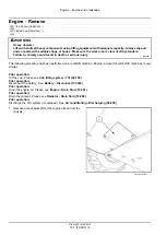
DANGER

Heavy objects!
Lift and handle all heavy components using lifting equipment with adequate capacity. Always support
units or parts with suitable slings or hooks. Make sure the work area is clear of all bystanders.
Failure to comply will result in death or serious injury.

D0076A

The following procedure has been performed on a radial lift machine. Engine installation for vertical lift machines is
very similar.

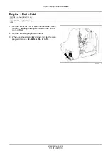
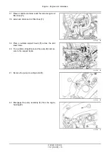
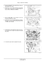
1. Attach proper lifting equipment to the front and rear

of the engine, and carefully lower the engine into the
chassis.

931001946

1

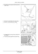
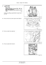
2. Orient the hydraulic pump coupler to the adapter on the

engine, ensuring the attachment of the engine plate to
the flywheel housing.

931001936

2

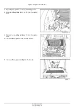
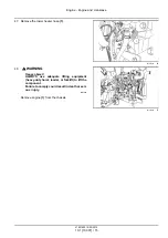
3. Apply

L

OCTITE

® 243™

to the threads of the mounting

bolts

(1)

for the hydrostatic drive assembly.

4. Install the mounting bolts and washers

(1)

into pump

housing. Torque the mounting bolts

(1)

for the hydro-

static drive assembly to

87 - 117 N·m

(

64 - 86 lb ft

).

931001928

3

47851950 14/05/2015

10.1 [10.001] / 16

Summary of Contents for 200 Series

Page 1: ... a trademark registered in the United States and many other countries owned by or licensed to CNH Industrial N V its subsidiaries or affiliates L221 L228 Tier 4B final 200 Series Skid Steer Loader L221 PIN NEM479941 and above L228 PIN NFM401546 and above C227 C232 Tier 4B final 200 Series Compact Track Loader C227 PIN NDM471836 and above C232 PIN NFM402195 and above ...

Page 2: ...3A F001 C232 TIER 4B FINAL North America F5HFL463A F001 C232 TIER 4B FINAL Europe F5HFL463A F001 L221 TIER 4B Final NEM479941 North America F5HFL463A F001 L221 TIER 4B Final NEM479941 Europe F5HFL463A F001 L228 TIER 4B FINAL Europe F5HFL463A F001 L228 TIER 4B FINAL North America F5HFL463A F001 47851950 14 05 2015 Find manuals at https best manuals com ...

Page 3: ...ly 19 1 Front axle system 25 25 450 Chain drive system 25 1 Rear axle system 27 27 650 Chain drive system 27 1 Hydrostatic drive 29 29 200 Mechanical control 29 1 29 218 Pump and motor components 29 2 29 202 Hydrostatic transmission 29 3 29 134 Two speed assembly 29 4 Brakes and controls 33 33 110 Parking brake or parking lock 33 1 Hydraulic systems 35 35 000 Hydraulic systems 35 1 35 300 Reservoi...

Page 4: ...ension 48 48 130 Track frame and driving wheels 48 1 48 100 Tracks 48 2 48 134 Track tension units 48 3 48 138 Track rollers 48 4 Cab climate control 50 50 100 Heating 50 1 50 200 Air conditioning 50 2 Electrical systems 55 55 000 Electrical system 55 1 55 010 Fuel injection system 55 2 55 011 Fuel tank system 55 3 55 012 Engine cooling system 55 4 55 019 Hydrostatic drive control system 55 5 55 0...

Page 5: ... controls 55 12 55 518 Wiper and washer system 55 13 55 640 Electronic modules 55 14 55 DTC FAULT CODES 55 15 Front loader and bucket 82 82 100 Arm 82 1 82 300 Bucket 82 2 Platform cab bodywork and decals 90 90 150 Cab 90 1 90 154 Cab doors and hatches 90 2 47851950 14 05 2015 Find manuals at https best manuals com ...

Page 6: ...47851950 14 05 2015 Find manuals at https best manuals com ...

Page 7: ...INTRODUCTION 47851950 14 05 2015 1 Find manuals at https best manuals com ...

Page 8: ...al safety 7 Torque Standard torque data for hydraulics 8 Basic instructions Shop and assembly 10 Torque Minimum tightening torques for normal assembly 12 General specification Biodiesel fuels 17 Capacities 20 Product identification 22 Product identification Machine orientation 24 See content for specific models 47851950 14 05 2015 2 Find manuals at https best manuals com ...

Page 9: ...components not approved by the manu facturer including those used for the servicing or repair of the product manufactured or marketed by the manufacturer In any case no warranty is given or attributed on the product manufactured or marketed by the manufacturer in case of damages caused by parts and or components not approved by the manufacturer The manufacturer reserves the right to make improveme...

Page 10: ...res to get into the soil Collect and dispose of coolant mixtures properly The air conditioning system contains gases that should not be released into the atmosphere Consult an air condi tioning specialist or use a special extractor to recharge the system properly Repair any leaks or defects in the engine cooling system or hydraulic system immediately Do not increase the pressure in a pressurized c...

Page 11: ...ult in death or serious injury CAUTION indicates a hazardous situation that if not avoided could result in minor or moderate injury FAILURE TO FOLLOW DANGER WARNING AND CAUTION MESSAGES COULD RESULT IN DEATH OR SERIOUS INJURY Machine safety NOTICE Notice indicates a situation that if not avoided could result in machine or property damage Throughout this manual you will find the signal word Notice ...

Page 12: ...INTRODUCTION Safety rules C227 NA C232 NA L221 NA L228 BT09A213 1 47851950 14 05 2015 6 ...

Page 13: ...eld conditions more weight may be required at the front or rear axle for adequate stability This is especially important when operating in hilly conditions or when using heavy attachments 9 Always lower the attachment shut off the engine set the parking brake engage the transmission gears remove the key and wait for all machine movement to stop before leaving the operators platform 10 If the attac...

Page 14: ...14 20 N m 10 15 lb ft 6 9 5 mm 3 8 in 9 16 18 29 33 N m 21 24 lb ft 20 27 N m 15 20 lb ft 8 12 7 mm 1 2 in 3 4 16 47 54 N m 35 40 lb ft 34 41 N m 25 30 lb ft 10 15 9 mm 5 8 in 7 8 14 72 79 N m 53 58 lb ft 47 54 N m 35 40 lb ft 12 19 1 mm 3 4 in 1 1 16 12 104 111 N m 77 82 lb ft 81 95 N m 60 70 lb ft 14 22 2 mm 7 8 in 1 3 16 12 122 136 N m 90 100 lb ft 95 109 N m 70 80 lb ft 16 25 4 mm 1 in 1 5 16 ...

Page 15: ...FACED FITTINGS When installing ORFS fittings thoroughly clean both flat surfaces of the fittings 1 and lubricate the O ring 2 with light oil Make sure both surfaces are aligned properly Torque the fitting to specified torque listed throughout the repair manual NOTICE If the fitting surfaces are not properly cleaned the O ring will not seal properly If the fitting surfaces are not properly aligned ...

Page 16: ...ation tool Do not tap the seal with a hammer or mallet 6 While you insert the seal check that the seal is perpendicular to the seat When the seal settles make sure that the seal makes contact with the thrust element if required 7 To prevent damage to the seal lip on the shaft position a protective guard during installation operations O ring seals Lubricate the O ring seals before you insert them i...

Page 17: ...d cable from the machine battery The electronic monitoring system and charging system will be damaged if this is not done 5 Remove the battery ground cable Reconnect the cable when you complete welding WARNING Battery acid causes burns Batteries contain sulfuric acid Avoid contact with skin eyes or clothing Antidote external Flush with water Antidote eyes flush with water for 15 minutes and seek m...

Page 18: ... m 163 lb in 25 N m 217 lb in 26 N m 234 lb in 35 N m 311 lb in 17 N m 151 lb in 24 N m 212 lb in M10 37 N m 27 lb ft 49 N m 36 lb ft 52 N m 38 lb ft 70 N m 51 lb ft 33 N m 25 lb ft 48 N m 35 lb ft M12 64 N m 47 lb ft 85 N m 63 lb ft 91 N m 67 lb ft 121 N m 90 lb ft 58 N m 43 lb ft 83 N m 61 lb ft M16 158 N m 116 lb ft 210 N m 155 lb ft 225 N m 166 lb ft 301 N m 222 lb ft 143 N m 106 lb ft 205 N m...

Page 19: ...9 N m 343 lb in 18 N m 163 lb in 27 N m 240 lb in M10 40 N m 30 lb ft 54 N m 40 lb ft 57 N m 42 lb ft 77 N m 56 lb ft 37 N m 27 lb ft 53 N m 39 lb ft M12 70 N m 52 lb ft 93 N m 69 lb ft 100 N m 74 lb ft 134 N m 98 lb ft 63 N m 47 lb ft 91 N m 67 lb ft M16 174 N m 128 lb ft 231 N m 171 lb ft 248 N m 183 lb ft 331 N m 244 lb ft 158 N m 116 lb ft 226 N m 167 lb ft M20 350 N m 259 lb ft 467 N m 345 lb...

Page 20: ...ft 7 16 48 N m 36 lb ft 65 N m 48 lb ft 68 N m 50 lb ft 91 N m 67 lb ft 50 N m 37 lb ft 71 N m 53 lb ft 1 2 74 N m 54 lb ft 98 N m 73 lb ft 104 N m 77 lb ft 139 N m 103 lb ft 76 N m 56 lb ft 108 N m 80 lb ft 9 16 107 N m 79 lb ft 142 N m 105 lb ft 150 N m 111 lb ft 201 N m 148 lb ft 111 N m 82 lb ft 156 N m 115 lb ft 5 8 147 N m 108 lb ft 196 N m 145 lb ft 208 N m 153 lb ft 277 N m 204 lb ft 153 N...

Page 21: ...85 lb ft 153 N m 113 lb ft 74 N m 55 lb ft 104 N m 77 lb ft 9 16 117 N m 86 lb ft 156 N m 115 lb ft 165 N m 122 lb ft 221 N m 163 lb ft 106 N m 78 lb ft 157 N m 116 lb ft 5 8 162 N m 119 lb ft 216 N m 159 lb ft 228 N m 168 lb ft 304 N m 225 lb ft 147 N m 108 lb ft 207 N m 153 lb ft 3 4 287 N m 212 lb ft 383 N m 282 lb ft 405 N m 299 lb ft 541 N m 399 lb ft 261 N m 193 lb ft 369 N m 272 lb ft 7 8 4...

Page 22: ...8 4 Grade Identification Grade Corner Marking Method 1 Flats Marking Method 2 Clock Marking Method 3 Grade A No Notches No Mark No Marks Grade B One Circumferential Notch Letter B Three Marks Grade C Two Circumferential Notches Letter C Six Marks 47851950 14 05 2015 16 ...

Page 23: ...fuel Do not use Biodiesel fuel has several positive features in comparison with diesel fuel Biodiesel fuel adds lubricity to the fuel which is beneficial in many circumstances particularly as sulfur and aro matics are removed from the fuel Biodiesel has a greater cetane number and burns cleaner Biodiesel produces less particulate matter and reduces smoke emissions Biodiesel is fully biodegradable ...

Page 24: ...vered for Warranty by NEW HOLLAND CONSTRUC TION Purchase biodiesel fuel from a trusted supplier who understands the product and maintains acceptable fuel quality It is highly recommended that you use biodiesel from BQ 9000 accredited suppliers to maintain the quality and con sistency of the fuel The BQ 9000 Quality Management Program is accredited by the National Biodiesel Board for producers and ...

Page 25: ...from your authorized NEW HOLLAND CONSTRUCTION dealer When switching back from biodiesel to regular 2 diesel all fuel filter oil and oil filter should be changed even if this falls between routine service intervals Storage The machine should not be stored for more than three months with biodiesel in the fuel system For longer storage time it is strongly suggested that only regular 2 diesel fuel is ...

Page 26: ...capacity 15 0 L 3 96 US gal System capacity L213 L216 29 9 L 7 9 US gal L218 L220 L221 C227 38 1 L 10 0 US gal L228 C232 45 4 L 12 0 US gal Specifications TUTELA AUTO SUPREME ENGINE OIL SAE 10W 30 Chain compartments Capacity each side L213 L216 6 25 L 6 6 US qt L218 L220 7 4 L 7 9 US qt L221 26 0 L 27 5 US qt L228 22 2 L 23 5 US qt Specifications TUTELA AUTO SUPREME ENGINE OIL SAE 10W 30 Grease fi...

Page 27: ...INTRODUCTION Final track drive Capacity each side 1 0 l 1 06 US qt 0 1 l 0 1 US qt Specifications TUTELA HYPOIDE EP GEAR LUBE SAE 80W 90 47851950 14 05 2015 21 ...

Page 28: ...ertical lift 9310748611 1 Inside left hand side loader arm tower radial lift 931002296A 2 Roll Over Protective Structure ROPS certification plate Front edge lower inside cab 931007505A 3 Engine serial number plate location for Models L213 and L216 On the fuel injection pump 76075756 4 47851950 14 05 2015 22 ...

Page 29: ...ne RAPH12SSL0406AA 5 Engine serial number plate location for Models L221 L228 C227 and C232 On the side of the Exhaust Gas Recirculation EGR cooler On top of the valve cover The serial number is also stamped on the engine front cover 23119866 6 Bucket identification plate BT04F026 01 7 47851950 14 05 2015 23 ...

Page 30: ...identification Machine orientation C227 C232 L221 L228 RAPH12SSL0057BA 1 The terms front 1 right 2 rear 3 and left 4 are used in this manual to indicate the direction as seen from the operator s seat 47851950 14 05 2015 24 ...

Page 31: ...SERVICE MANUAL Engine C227 TIER 4B Final NDM471836 C232 TIER 4B FINAL L221 TIER 4B Final NEM479941 L228 TIER 4B FINAL 47851950 14 05 2015 10 ...

Page 32: ...case 10 1 10 216 Fuel tanks 10 2 10 501 Exhaust Gas Recirculation EGR Diesel Particulate Filter DPF exhaust treatment 10 3 10 400 Engine cooling system 10 4 10 414 Fan and drive 10 5 10 304 Engine lubrication system 10 6 47851950 14 05 2015 10 ...

Page 33: ...Engine 10 Engine and crankcase 001 C227 TIER 4B Final NDM471836 C232 TIER 4B FINAL L221 TIER 4B Final NEM479941 L228 TIER 4B FINAL 47851950 14 05 2015 10 1 10 001 1 ...

Page 34: ...Contents Engine 10 Engine and crankcase 001 SERVICE Engine Drain fluid 3 Remove 4 Install 16 Filling 27 See content for specific models 47851950 14 05 2015 10 1 10 001 2 ...

Page 35: ...L228 1 Remove the access cover at the rear lower left of the machine exposing the engine oil drain hose and re mote oil filter 2 Remove the drain plug to drain the oil 3 When the oil has completely drained reinstall the drain plug and torque to 68 82 N m 50 61 lb ft 63109370 1 47851950 14 05 2015 10 1 10 001 3 ...

Page 36: ...procedure has been performed on a radial lift machine Engine removal for vertical lift machines is very similar Prior operation Tilt the cab Please see Cab tilting system Tilt 90 150 Prior operation Disconnect the battery See Battery Disconnect 55 302 Prior operation Drain the engine oil Please see Engine Drain fluid 10 001 Prior operation Drain the coolant Please see Radiator Drain fluid 10 400 P...

Page 37: ...H12SSL0232AA 2 3 Remove the mounting bolts for the overflow bottle 4 Remove the overflow bottle from the chassis RAIL14SSL0845BA 3 5 If equipped with A C disconnect the A C lines 1 from the condenser 6 Disconnect the fan motor 2 from the wiring harness RAPH12SSL0075AA 4 47851950 14 05 2015 10 1 10 001 5 ...

Page 38: ... 8 Disconnect the engine hood strut 1 from the engine hood RAPH12SSL0074AA 5 9 Remove the mounting hardware 2 from the engine hood 10 Remove the engine hood 1 from the chassis RAPH12SSL0073AA 6 11 Remove the engine cover 1 from the chassis 931001899 7 47851950 14 05 2015 10 1 10 001 6 ...

Page 39: ...d RAPH12SSL0067AA 8 13 Disconnect the upper radiator hose 1 from the radi ator RAPH12SSL0065AA 9 14 Disconnect the lower radiator hose 1 from the radia tor NOTE The rear access door has been removed for picture clarity RAPH12SSL0083AA 10 47851950 14 05 2015 10 1 10 001 7 ...

Page 40: ...ankcase 15 Remove the radiator 2 from the shroud 16 RAPH12SSL0066AA 11 17 Remove the radiator fan 1 from the engine RAPH12SSL0062AA 12 18 Unbolt and remove the shroud 1 RAPH12SSL0264AA 13 47851950 14 05 2015 10 1 10 001 8 ...

Page 41: ...1 retaining the mounting flange for the muffler inlet pipe to the turbocharger 931001896 15 21 Remove the retaining bolts 1 from the muffler sup port 22 Remove the muffler 931001895 16 23 Disconnect the air restriction sensor 1 from the wiring harness 931002030 17 47851950 14 05 2015 10 1 10 001 9 ...

Page 42: ... the tube 1 for the air cleaner and tur bocharger 931001898 18 26 Remove the air cleaner housing 1 from the chassis 931001900 19 27 Disconnect the alternator 1 from the wiring harness 931001908 20 28 Disconnect the starter 1 from the wiring harness 931001909 21 47851950 14 05 2015 10 1 10 001 10 ...

Page 43: ...e starter 2 931001910 22 30 Remove the oil filler neck 1 from the engine 31 If equipped with A C disconnect the low pressure line 2 on the A C compressor RAPH12SSL0266AA 23 32 Disconnect the fuel return line 1 on the tank RAPH12SSL0053AA 24 47851950 14 05 2015 10 1 10 001 11 ...

Page 44: ...l filter hous ing RAPH12SSL0054AA 25 34 Disconnect the engine harness connectors 1 RAPH12SSL0052AA 26 35 Disconnect the fuel temperature sensor 1 from the wiring harness 36 Disconnect the fuel feed line 2 from the engine RAPH12SSL0055AA 27 47851950 14 05 2015 10 1 10 001 12 ...

Page 45: ...lter lines 1 931001923 28 39 Place a suitable support beam 1 across the skid steer frame 40 Tie a suitable strap 2 around the pump 3 and se cure to the support beam 931001929 29 41 Remove the pump mounting bolts 1 931001928 30 42 Disengage the pump assembly 1 from the engine housing 2 931001936 31 47851950 14 05 2015 10 1 10 001 13 ...

Page 46: ...ilure to comply will result in death or serious injury D0018A Attach proper lifting equipment 1 to support the en gine 2 931001944 32 44 Remove the front and rear engine mounts bolts 1 931001933 33 45 Remove heater hose clamp 1 931001943 34 46 Remove upper heater hose 1 931002114 35 47851950 14 05 2015 10 1 10 001 14 ...

Page 47: ...0 36 48 WARNING Heavy object ALWAYS use adequate lifting equipment heavy duty hoist loader or forklift to lift the component Failure to comply could result in death or seri ous injury W0101A Remove engine 1 from the chassis 931001946 37 47851950 14 05 2015 10 1 10 001 15 ...

Page 48: ...al lift machine Engine installation for vertical lift machines is very similar 1 Attach proper lifting equipment to the front and rear of the engine and carefully lower the engine into the chassis 931001946 1 2 Orient the hydraulic pump coupler to the adapter on the engine ensuring the attachment of the engine plate to the flywheel housing 931001936 2 3 Apply LOCTITE 243 to the threads of the moun...

Page 49: ...2047 4 7 Apply LOCTITE 243 to the threads of the front mounting bolts 2 for the engine 8 Install the two front mounting bolts 2 and bushings for the engine Torque the front mounting bolts 2 to 163 176 N m 120 130 lb ft 931001933 5 9 Verify that the mounting bolts for the pump are secure and carefully remove support brace 4 and straps 5 from pump 931001929 6 10 Connect the lower heater hose 6 to th...

Page 50: ...t the two remote lines 12 13 for the oil filter 931001923 9 13 Connect the fuel temperature sensor 1 to the wiring harness 14 Connect the fuel feed line 2 to the engine RAPH12SSL0055AA 10 15 Connect the engine harness connectors 1 to the en gine RAPH12SSL0052AA 11 47851950 14 05 2015 10 1 10 001 18 ...

Page 51: ...This as a preview PDF file from best manuals com Download full PDF manual at best manuals com ...

Reviews: