
D-422-MG
Rev.
0
10
3.5
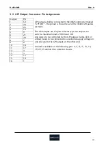
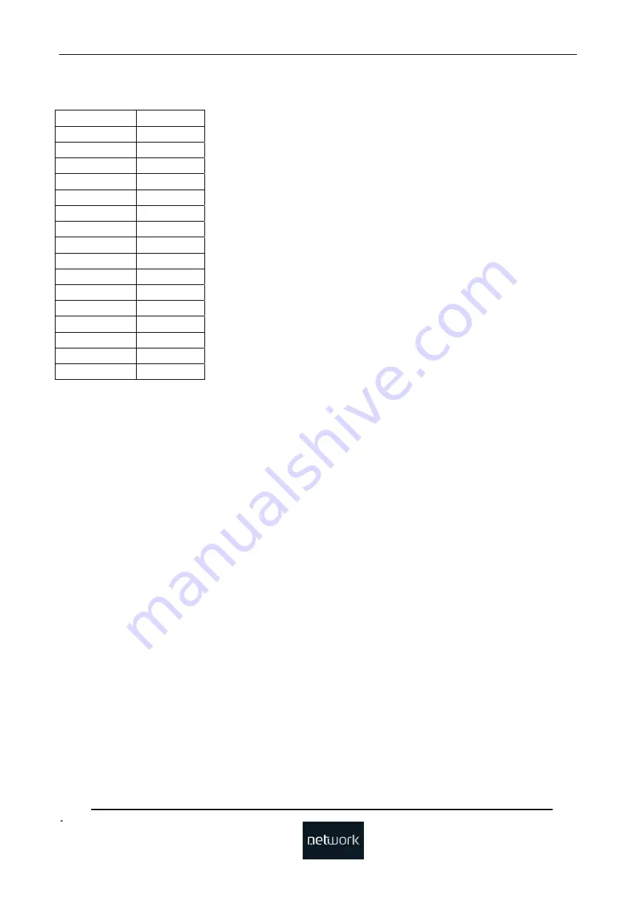
GPI Output Connector Pin Assignments
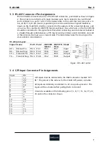
GPI outputs shall be connected to the DB25 connector marked
“GPI OUT”. The pinout is the same as for the VikinX GPI panels,
see table.
The GPI outputs are of open collector type. An output can
switch a maximum load of 100mA at 30V.
Any device to be controlled by the GPI outputs (lamp, LED or
similar) needs to be connected to an external supply voltage on
one end and to the GPI output on the other end.
Ground is available on the following pins: 2, 5, 8, 11, 13, 16,
19, 22, 25 and on the connector chassis.
Output Pin
1 12
2 24
3 23
4 10
5 9
6 21
7 20
8 7
9 6
10 18
11 17
12 4
13 3
14 15
15 14
16 1


