background image


Page 167/ 191 

2.  NW6010 Bridge Control Unit 


2.1 General 


The Bridge Control Unit (BCU) serves both as an interface for serial/NMEA data as well to display 
the  operational  status  and  provide  user  functionality  like,  but  not  limited  to,  operational 
performance tests. 


2.2 Location and mounting 


The  BCU  may  be  mounted  in  a  protected  environment  at  any  convenient  location  taking  into 
account the compass safe distance as indicated on the unit. 


2.3 Indicators 


The BCU has 1 LED at the back to indicate that the power supplied to it is present, in other words, 
at least a PoE link is established to the core module. In the event the LED is illuminated (steady, 
green), the video display on the unit must work.  


Furthermore, each network-port provides Link and Activity LEDs on the backside of the unit with 
following meaning.  
 
Link speed (Green LED); the LED is on when there is a link connection, otherwise, the LED is off.  
 
Activity (Yellow LED); the LED is flashing when there is activity on the link; otherwise, the LED is 
off. 


2.4 Errors 


Error indication: in the event the LED on the back side of the unit is On, the display is illuminated 
and showing text (buttons), but no valid (UTC) time is presented on the display, the data-link to 
the core module is not functional at that time. All other errors are presented on the display. 


The BCU provides an Auxiliary ALERT relay of which the (dry) contact rating is 28V dc, 200mA 
max. During a correct functioning of the VDR, the relay contacts are in the NO position. When an 
ALERT condition occurs or the VDR loses its power, the NC position is valid. (NC=normally closed, 
CO=COMMON contact, NO=normally open). 


2.5 Operating instructions 


The BCU is equipped with a touch screen display with day and night display mode. 


Summary of Contents for NW6000

Page 1: ......

Page 2: ...ranslated or stored in any form or by any means duplicated and or published by means of photocopy microfilm storage in computer files or otherwise which also applies to full or partial processing with...

Page 3: ...INCL LWE 27 2 5 1 IP ADDRESS FOR ASSIGNMENT 28 2 5 2 SPECIFICATIONS FOR VIDEO USING LIGHT WEIGHT ETHERNET IEC 61162 450 28 2 6 MULTICAST ADDRESS RANGE 29 2 6 1 UDP MULTICAST PROTOCOL 29 2 6 2 USE OF M...

Page 4: ...8 2 LOCATION AND MOUNTING 46 8 3 POWER 48 8 4 CONNECTIONS 48 8 5 AUDIO SIGNALS 48 8 6 INDICATOR 49 8 7 ERRORS 49 8 8 CONFIGURATION 49 8 9 OPERATING INSTRUCTIONS 49 9 NW6031 AUDIO HUB 50 9 1 GENERAL 5...

Page 5: ...AL SPECIFICATIONS 87 11 2 LOCATION AND MOUNTING 89 11 3 CONNECTION TEST WITH FLYING CABLE 93 11 4 JUNCTION BOX 94 11 4 1 GROUNDING OF CABLES AND JUNCTION BOX 94 11 4 2 WIRE SCHEMATIC JUNCTION BOX 96 1...

Page 6: ...16 8 CONFIGURATION 117 16 9 OPERATING INSTRUCTIONS 117 17 NW64308 16 24 DIGITAL 8 16 24 CHANNEL ADAPTORS 117 17 1 GENERAL 117 17 2 MOUNTING 117 17 3 POWER SUPPLY 118 17 4 CONNECTIONS 119 17 5 DATA COM...

Page 7: ...ANCED SETTINGS 149 22 6 ANALYZE TOOL 150 22 7 BAM TOOL 151 22 8 REBOOTING THE VDR 152 23 BAM INTERFACE SPECIFICATION 153 23 1 BRIDGE ALERT MANAGEMENT BAM 153 23 2 MANUFACTURER ID 153 23 3 SUPPORTED NM...

Page 8: ...2 7 7 HARDWARE MALFUNCTION 170 2 8 OPERATING SCREENS 170 2 9 ALERT LOGGING 171 2 10 SOFTWARE VERSION RECOGNITION 171 2 11 SCREEN TEST 172 3 NW6880 TRON 40VDR FRM FLOAT FREE CAPSULE 173 3 1 GENERAL 173...

Page 9: ...Page 9 191 8 1 RMRS RULES FOR EQUIPMENT DECOMMISSIONING 187 9 ANNEX II ENERGY SAVING 189 9 1 VDR PCB CONTROLLERS 189 9 2 POWER CONSUMPTION CALCULATION 189 10 ANNEX III EQUIPMENT LABELLING RMRS 190...

Page 10: ...and Operator and maintenance manual Part 1 Installation manual NW6000 00 This part covers all physical and wiring aspects of the VDR installation up until the moment the system is powered up and inclu...

Page 11: ...et 2 3 Update to include new functionalities in v1 6 3 24th of April 2020 HdH 2 4 reviewed and updated changes from 2 3 5th June 2020 HdH JA 2 5 added BAM specification added PSU v2 added Player V2 8t...

Page 12: ...Addition in section 14 about new Docking Module 83180 MkII new wire scheme and new led indication 24th of August 2016 C van t Riet 1 11 Declaration of Conformity enclosed section 2 3 Clarifications fo...

Page 13: ...age Data Recorder is operational unless fully qualified to do so Only NetWave Systems Certified Technicians should undertake work on the system A current of 100 mA passing through the human body for o...

Page 14: ...n individual allergic reactions Components which are broken or overheated may release toxic fumes or dust and must be treated with caution Do not inhale the fumes and ensure that the dust and debris d...

Page 15: ...ion IMO International Maritime Organization INS Integrated Navigation System IP Internet Protocol LCD Liquid Crystal Display LED Light Emitting Diode NMEA National Marine Electronic Association PC Per...

Page 16: ...Page 16 191 VDR Voyage Data Recorder VESA Video Electronics Standards Association VHF Very High Frequency VRM Variable Range Marker...

Page 17: ...ets all the requirements of a satellite EPIRB as required by the carriage requirements of SOLAS IV and all the requirements of a VDR as required by the carriage requirements of SOLAS V Configuration D...

Page 18: ...tware Copy of the software program to provide the capability to download the stored data and play back the information The software should be compatible with an operating system available with commerc...

Page 19: ...SC 163 78 Performance standards for ship borne simplified voyage data recorders S VDR IMO MSC 333 90 Adaption of revised performance standards for Ship borne Voyage Data Recorders VDRs Eurocae ED56A M...

Page 20: ...1993 2 Maritime navigation and radio communication equipment and systems Automatic identification systems AIS Part 2 Class A ship borne equipment of the universal automatic identification systems AIS...

Page 21: ...decision will need to be taken by the flag State in co operation with any other substantially interested States on the viability and cost of recovering the VDR balanced against the potential use of th...

Page 22: ...n will be governed by the applicable domestic legislation of the flag State coastal State and other substantially interested States as appropriate and the guidelines given in the Code for the Investig...

Page 23: ...erformance Test as described in the chapter Routine maintenance Operator and maintenance manual Please download the data set as described in Download data set from the VDR system Operator and maintena...

Page 24: ...47 0 5 Powered using PoE 2 line in Interface for microphones Bulkhead mounted IP20 Hardened FRM NW6860 411 x 311 27 5 Powered thru PoE from core module Deck mounted protective capsule for 48 days IP68...

Page 25: ...dule receives and processes any item of information received from the sensors directly or via an interface and distributes that data which is monitored for integrity and compressed to all Final Record...

Page 26: ...6410 WaveNet Buscoupler in conjunction with NW 64208 NMEA adaptor unit or VDR sensor i e microphone and stored onto multiple recording media Since most data is converted and formatted within the inter...

Page 27: ...6 14 Watertight and fire door status 4 6 15 Accelerations and hull stresses 4 6 16 Wind speed and direction 4 6 17 AIS 4 6 18 Rolling motion 4 6 19 Configuration data 2 4 Power failure All available...

Page 28: ...use 172 16 30 1 to 172 16 30 254 subnet mask 255 255 0 0 networks outside this range are also permissible and are detected during the initial probe It is not required to set the IP address of an LWE s...

Page 29: ...Dynamic Port range that IANA has reserved for dynamic and or private port numbers range 49152 to 65535 inclusive Any port numbers used may be derived from the VDR configuration utility 2 7 Cabling re...

Page 30: ...max 100m unless otherwise specified in cable diagram Cable screen must be grounded unless otherwise specified on connection diagram Length is measured from cable entrance socket to cable entrance sock...

Page 31: ...DR is provided with ample grounding points Please ensure that these grounding points are being used according standard installation practices Power the VDR and name the recording channels which are to...

Page 32: ...channel NW6880 FRM Float Free Capsule Jotron TRON 40 NW6860 1000 FRM Final Recording Medium fixed SS Capsule NW6890 FRM PoE Splitter Box f HVR04 NW6410 WaveNet Buscoupler NW64208 Serial NMEA 8 CH adap...

Page 33: ...power as per IEC61996 1 2013 are included within this enclosure The batteries are accessible by removing the top cover of the unit The batteries need to be replaced every two years 5 2 Location and mo...

Page 34: ...core mains 3x1 5 mm2 braided flame retardant halogen free The power connector and cable are provided within the standard scope of supply and indication for the position for the L Brown N Blue and GND...

Page 35: ...switch to completely power down the system The system can be powered up again using the mains ON OFF switch on the PSUv2 or re inserting the PSU v1 module 5 4 Ethernet The Core module has 10x Etherne...

Page 36: ...Q IEC61162 450 LWE IEC62338 PoE 802 3af CMF 1 6 optional sensor data i e DAQ IEC61162 450 LWE IEC62338 PoE 802 3af CMF 1 7 optional sensor data i e DAQ IEC61162 450 LWE IEC62338 PoE 802 3af CMF 1 8 op...

Page 37: ...N Bridge Alarm management systems to register the VDR internal CAUTIONs The VDR CAUTION does not reflect any CAUTIONs external to the VDR itself i e of sensors or equipment connected thereto 5 6 Data...

Page 38: ...ion otherwise the LED is off Yellow LED LED is flashing when there is activity on the link Otherwise the LED is off 5 8 Errors If errors occur within the Core Module these will be indicated on the dis...

Page 39: ...e compass safe distance as indicated on the unit Prepare the location by cutting out a rectangle of 130x80 mm as well as 4 smaller rectangles as per the drawing below Tip Use the metal frame supplied...

Page 40: ...NC position is valid NC normally closed CO COMMON contact NO normally open NMEA connections to the BCU are to be connected as follows Connector Data rate N1 NMEA channel 1 A 4k8 38k4 N2 NMEA channel 1...

Page 41: ...al NMEA ALARM Fig 6 4 Bridge Control Unit interfacing connections back view 6 5Data communications The Bridge Control Unit fully relies on Ethernet connections to Core Module and has to be configured...

Page 42: ...ck side of the unit is ON the display is illuminated and showing text buttons but no valid UTC time is presented on the display the data link to the core module is not functional at that time All othe...

Page 43: ...ce may be placed in a protected environment at a location most practical to realize the connections 7 2Power supply This is powered using PoE 7 3Connections 1 The NW6060 VHF Audio Interface is connect...

Page 44: ...oadcast must be completed NOTE When broadcasting on VHF ensure that no transmissions are made that could be confused with anything other than a test transmission The voice test should be performed fro...

Page 45: ...est 5 Download a small data set using the VDR Player software 6 Playback the data to ensure both transmit and receive data is recorded properly It is advised that you combine live microphone sound rec...

Page 46: ...Differential analogue output On board microphone and sound test capability Green LED indicator for location and audio test indication 8 2Location and mounting One or more microphones positioned on th...

Page 47: ...e screw cover this enables easier removal of the screw cover cap if necessary during the service life of the microphone The rubber seals provided with the microphones are used to minimize vibrations b...

Page 48: ...ividually connected to the NW6031 Audio Hub Only one microphone can be connected to an NW6031 Audio Hub channel Paralleling of microphones into Audio Hub channels is prohibited and will result in the...

Page 49: ...lly OFF 8 7Errors If errors occur these will be indicated on the display of the Bridge Control Unit 8 8Configuration The microphone adopts the input that the microphone is connected to on the NW6031 A...

Page 50: ...er NW6031 or VHF inputs 9 2Location and mounting One or more NW6031Audio Hubs may be used with the NW6000 The NW6030 requires a PoE connection with a maximum cable distance from the NW6000 of 100m The...

Page 51: ...ote Connections to microphones also require using the provided ferrite clamps on both ends of cable Cable needs to be looped as indicated in the drawing 9 5Indicator The NW6031 has no external indicat...

Page 52: ...functions All inputs default to NW6031 Analogue Microphone input by default after probing for the first time These can be changed via the configurator for VHF inputs if required 9 8Operating instructi...

Page 53: ...o resolution interlacing refresh rate etc With each video interface a USB memory stick is provided with the Video Configuration Suite VCS2 application which must be used to configure the video interfa...

Page 54: ...o strips of DIN Rail must be installed The module is held in place with clips on the back NOTE The DIN Rail is NOT supplied with the Video Module Figure 10 2 1 Video Module DIN Rail Clips Alternative...

Page 55: ...deo DB 15HD input Video4 Channel 4 Video DB 15HD input Table 9 4 B Video Module Back Panel Connection In cases where the video module is not co located with its video source the following video cable...

Page 56: ...10 8 PC set up To set up the Video Module a service PC should be connected to the module LAN connection and run the VCS2 remotely To make this connection complete the steps below 1 Connect the laptop...

Page 57: ...button 6 Press OK a Press OK in the Advanced Settings window b Press OK in the Windows Firewall window c Press Close in the Local Area Connection Properties window d Install VCS2 on the Service PC e...

Page 58: ...ue Remarks HsRate1 80 0 HSYNC rate in kHz for default source Pclk1 135 0 The exact pixel clock frequency in MHz for the system as specified by the display s manufacturer VCO1 2 Normally set based on t...

Page 59: ...ent and must be same value as in CLOCK section CPmp1 6 Must be present and must be same value as in CLOCK section N1 0 Must be present and must be same value as in CLOCK section Table 9 10 B SYNCS Par...

Page 60: ...nitial images If a video capture does not initiate the most likely reason is that the VPOL1 field may be set wrong The Video Configuration Utility VCS2 if provided with a channel number will capture a...

Page 61: ...tection routine which detects many of the necessary parameters for the VidChanX ini files Existing VidChanX ini files can also be directly modified within this application Figure 10 11 1 Video Configu...

Page 62: ...r the current channel click the Restore Default Settings button If the auto detection is successful the image will be displayed in the Capture area and the Auto Detection Status configuration data fie...

Page 63: ...image Complete the following steps to establish the correct Horizontal Polarity setting 1 Click the Video Configuration Utility s tab Configuration to open the Configuration page 2 In the Polarity Sec...

Page 64: ...y must be adjusted Figure 10 14 1 Correct vertical polarity on left Vertically skewed image on right Once the image has been captured complete the following steps to correct the vertical polarity sett...

Page 65: ...st the captured image so that it completely fills the entire capture window The image should be adjusted so that it is as close as possible to the top and left edges of the capture window to set the l...

Page 66: ...for the X and Y values in the Horizontal Vertical Offset section of the Sizing page NOTE 1 Horizontal X Offset must be a multiple of 8 It is recommended to leave a small amount of black space to help...

Page 67: ...To adjust the image size 1 Click the Start button on the Dimensions section of the Sizing page 2 The following warning will be displayed Figure 10 17 1 Adjusting the Image Size Warning 3 Click Okay an...

Page 68: ...ber by a Entering the desired width in the New Dimensions Width scroll box Must be multiple of 8 b Entering the desired height in the New Dimensions Height scroll box 8 Click the Apply button in the l...

Page 69: ...18 1 Interlaced image 1 On the Configuration Page set the Vertical Polarity to the same setting negative or positive as indicated in the Auto Detection Information Box 2 Repeat for the Horizontal Pol...

Page 70: ...Click the Sizing tab to open the Sizing page ii Click the Start button in the Dimensions section iii Increase the image height to make this lower image visible iv Adjust the Image Dimensions as writt...

Page 71: ...on of the Sizing page ii Decrease the Vertical Offset NOTE In most cases the Vertical Offset value will only need to be decreased slightly for example if the setting is 24 adjust to 16 6 Zoom in on up...

Page 72: ...corrected or the image s numbers look blurry see figure below it is very likely the installer chose the wrong pixel coordinates That means the image is interlaced incorrectly To correct the interlacin...

Page 73: ...correcting the image Figure 10 18 5 Incorrectly Interlaced image To achieve the optimal image capture After properly interlacing the image the installer may need to adjust the Sizing page s Horizontal...

Page 74: ...ction 3 Use the New Offset X scroll box and Y scroll box to change the horizontal and vertical offsets to move the image as close to the top left hand corner of the Capture window as possible as given...

Page 75: ...ease the height of the image click Yes in most cases the image height will be too small 7 Zoom into the image 8 If the image does not look correct adjust Line 1 Start one value at a time until it look...

Page 76: ...ct then this section can be skipped But if the installer can see a skewed circle or if the image has the wrong aspect ratio then the captured image may need recalibration Use the following steps to re...

Page 77: ...ply button 5 This applies the adjusted value of the Phase Lock Loop PLL Multiplier Number N and recalibrates the captured image 6 If the recalibrated image has improved but needs further recalibration...

Page 78: ...he true upper left corner of the captured image The installer may have to adjust the image s position several times to ensure it is as close as possible to the top left corner without losing any part...

Page 79: ...ments tab to open the Adjustments page This page includes 4 sections including 1 Sharpness 2 Gain Offset Adjustment 3 Clamp 4 Coast In these for sections the installer will find all the controls neede...

Page 80: ...image quality is achieved 10 22 2 CPMP Charge Pump When the image phase is sharpened minor oscillation may still appear in the image If so it may be necessary to adjust the image CPMP Check for oscill...

Page 81: ...taller can fine tune the gain and or offset in the Gain Offset Adjustment section This section includes a histogram red Green and Blue Gain and Offset controls and a Master Gain and Master Offset cont...

Page 82: ...window is fine tuned To fine tune the Gain and Offset using the Master Gain and Offset scroll buttons Adjusting Gain stretches the image vertically in the Capture window 1 Click on the Master Gain scr...

Page 83: ...e the following parameters CLOCK HsRate1 xx xxx XDim1 512 YDim1 800 SYNCS Source1 AD9887 N1 yyyy The HSYNC value HsRate1 xx xxx can be obtained from the Video Config Suite application The overall x di...

Page 84: ...tab page and click Save VidChanX ini file to save the settings 10 27 Info Tab Selecting the Info tab of the Video Configuration Utility opens the Info page It provides statistics on the capture image...

Page 85: ...e image o Fit to Window Will cause the image the edges of the image to fill to the edges of the Image window o Full Screen This sets the Video Configuration Utility to Full Screen mode Right click on...

Page 86: ...rrectly If not stop recording and make the necessary changes to the configuration a If the top edge of the image capture is not captured correctly go to the VidChanX ini file and increase the value as...

Page 87: ...Besides this the user manual is enclosed to the delivery box of the TRON 40VDR and can be found on the internet site of Jotron as well According to the IEC61996 1 2013 MSC 333 90 5 4 3 recording of th...

Page 88: ...al power budget is 4 Watts The unit fully relies on Ethernet connections to the Core Module and provide datas within the VDRs specified commissioned IP range refer to Network configuration The unit mu...

Page 89: ...est with flying cable Take following aspects into account for choosing the mounting location of the TRON 40VDR It is not recommended to locate the TRON 40VDR on the compass deck because of high risk o...

Page 90: ...functioning of the TRON 40VDR It is critical to choose a position where the released EPIRB will not get trapped by overhangs rigging antennas and so forth in case the vessel will sink The EPIRB is sup...

Page 91: ...Page 91 191...

Page 92: ...Page 92 191...

Page 93: ...the new position and run the ping utility in CMD by typing the following command hrping exe 172 16 30 10 t w 100 s 15 y 10 gg Note run hrping exe by entering the full path name C hrping exe 172 16 30...

Page 94: ...f the junction box Therefore firstly strip off 7 cm of the cables to create 7 cm of grounding shield Separate the grounding shields from the cables Do not remove the grounding shields Place the ground...

Page 95: ...Page 95 191 To ensure water tightness make sure the cable glands are tightened well and the provided vulcanizing tape is placed around the 2 cable glands as shown on picture below...

Page 96: ...docking module can be found as indicated on picture below this is not the serial number of the VDR EPIRB Cable type 1 TRON 40VDR Cable type 2 TRON 40VDR Connect the TRON 40VDR to the VDR via the junct...

Page 97: ...er 2017 VDR side Connector pin TRON 40VDR side Rx White orange 1 White orange Rx Rx Orange 2 Orange Rx Tx White green 3 White green Tx Tx Green 4 Green Tx N A Not connected 5 White blue Connected but...

Page 98: ...on box without replacing it Some copper slip or other water dispersing formula can also be used 11 5 Led indicators on docking module Below is a description of the LED lights on the Docking Module 831...

Page 99: ...ation due to spray rain hosing off The HSS memory module protective capsule is painted a highly visible fluorescent orange with the required text VOYAGE DATA RECORDER DO NOT OPEN and REPORT TO AUTHORI...

Page 100: ...ad block management Dynamic and static wear levelling Wear levelling algorithm that provides more than 5 million write erase cycles for reliable data storage over an extended period The Hardened Stora...

Page 101: ...e capsule to allow an ROV or diver to work Compass safe distance 60 cm The HSS consists of two sub assemblies A deckmount sub assembly is directly fastened to the ship and provides watertight cable en...

Page 102: ...d underneath the quick release mechanism after connecting the cable to CPU of the storage medium A Deckmount Install the stainless steel deck mount on a suitable place using the supplied bolts as per...

Page 103: ...PU housing as below E Once the storage medium and the deckmount are placed upon each other attach the vulcanized tape around the flanges to ensure water tightness Stretch around 50cm of vulcanized tap...

Page 104: ...a link connection Otherwise when no power is received the LED is off Activity Yellow The LED is flashing when there is activity on the link Otherwise the LED is green Error Red The LED is steady when...

Page 105: ...inued operation recording of specific data during a power failure In that case the PoE power will be available for two hours NW 6000 Core Module Refer to N6 001 2 Single wire PoE ethernet cabling FRM...

Page 106: ...Page 106 191 13 4 Connections Ethernet OUT Ethernet IN fm Core Module PoE SHIELD Ethernet OUT to HVR04 24V OUT to HVR04 PoE IN 24 VDC OUT to PD powered device...

Page 107: ...er The DAQ system relies on the busbar integrated within the DIN rail serving the function of power and data distribution Within the DAQ the so called WaveNet Buscoupler plays a vital role since it ha...

Page 108: ...the Ethernet PoE supplied from the Core Module This unit has 1 x 100 TX PoE ports receiving 802 3af compliant PoE 48V The total power budget is 12 Watts 14 4 Connections From the DAQ containing the Bu...

Page 109: ...and wiring identification scheme Please note that there are 3 different sizes of adaptors depending on port characteristics and number of ports with a varying number of connectors and wires Consequent...

Page 110: ...te the largest width adaptor is shown with connectors in rows A B and C Smaller adaptors with less channels will have 1 row A or 2 rows A and B Top rows are identified by a T prefix whereas the bottom...

Page 111: ...nder the feathering contacts between the module and the DIN useless and the system will fail beyond repair 15 3 Power supply This unit has 1 x 1000 TX PoE port receiving 802 3af compliant PoE 48V and...

Page 112: ...r otherwise Channel 1 NMEA IEC61162 2 input port 4k8 up to 38K4 Bd Channel 2 NMEA IEC61162 2 input port 4k8 up to 38K4 Bd Channel 3 NMEA IEC61162 2 input port 4k8 up to 38K4 Bd Power A Power IN 24 VDC...

Page 113: ...62 450 compliant 15 7 Indicators Led Function PWR Power supply to DIN Busbar established Link Connected to Core Module Data Communications PoE Power Supply by PoE OK 15 8 Errors If errors occur within...

Page 114: ...the busbar backplane for further processing by the Buscoupler which in its turn streams the data onto the VDR network 16 2 Mounting These adaptors connect to the DIN busbar within the DAQ enclosure by...

Page 115: ...Page 115 191 16 4 Connections For physical connector and wiring identification please refer to the figures below Figure 16 4 1 Connection figure NMEA Module 8 channels...

Page 116: ...Page 116 191 Figure 16 4 2 Connection figure NMEA Module 16 channels Figure 16 4 3 Connection table NMEA Modules...

Page 117: ...me associated with the physical connection during the commissioning process 16 9 Operating instructions After commissioning of the VDR system this unit does not require crew operating instructions 17...

Page 118: ...ceive their power indirect PoE converted to 24V DC via the DIN rail mounted NW6410 Buscoupler Please note that for digital contacts additional 24 VDC will need to be supplied from either separate powe...

Page 119: ...Page 119 191 17 4 Connections For physical connector and wiring identification please refer to the figures below Figure 17 4 1 Connection figure Digital Module 8 channels...

Page 120: ...Page 120 191 Figure 17 4 2 Connection figure Digital Module 16 channels...

Page 121: ...Page 121 191 Figure 17 4 3 Connection figure Digital Module 24 channels...

Page 122: ...nd each row of 8 channels has a LINK led which indicates if that part of the adaptor has power and has established a data link with the Buscoupler 17 7 Errors If errors occur within the adaptor these...

Page 123: ...nt measurement 18 2 Mounting These adaptors connect to the DIN busbar by mounting them from the top first and only in a vertical direction Once the adaptor is attached to the DIN rail it should not be...

Page 124: ...g upon which connector entry is chosen a choice is made between voltage and current measurement For physical connector and wiring identification please refer to the figures below Figure 18 4 1 Connect...

Page 125: ...Page 125 191 Figure 18 4 2 Connection figure Analogue Module 8 channels...

Page 126: ...Page 126 191 Figure 18 4 3 Connection figure Analogue Module 12 channels...

Page 127: ...16 24 and each row of 8 channels has a LINK led which indicates if that part of the adaptor has power and has established a data link with the Buscoupler 18 7 Errors If errors occur within the adaptor...

Page 128: ...ysically connecting to the VDR The VDR s Ethernet ports on the Core Module are auto sensing and you should not have to change your Ethernet cable however if you encounter problems obtaining access to...

Page 129: ...6000 orolia local Before configuring the VDR it is important to get an understanding and check of all connected sensors to the VDR For this purpose the VDR Web Server provides an NMEA Analyzing tool O...

Page 130: ...rname and password Configuration of the VDR settings is available for authenticated users Changes are committed to the VDR by saving them once they have been configured Once saved the VDR will reboot...

Page 131: ...assword available to certified service engineer The current configuration for the VDR is available when the Configuration page opens Select Probe to show currently installed devices Select SCAN to sca...

Page 132: ...132 191 Configuration will start vessel particulars to be filled A Vessel name IMO and MMSI numbers must be filled B Start with the configuration of the VDR system These are Video Audio and NMEA sour...

Page 133: ...Perform the same method for setting up the Digital Signals PN2xxx are used for the VHF module insert desired names for the channels PN4xxx are used for the NW6030 Analogue Microphones connected to an...

Page 134: ...ocation on the vessel in General Settings In the additional notes field please add the required z coordinate measured from high water line Additional VDR critical sensors are configured in Critical Se...

Page 135: ...ources Add categories for groups of NMEA OPT items Dragging or double clicking the NMEA sources will add that item to the currently selected category OPT categories will become visible on the BCU once...

Page 136: ...VDR will now search for all available video channels 4 The video channels will become visible in the NEW DEVICES list based on the configured identifiers i e EC0001 and RA0001 Add these to the INSTAL...

Page 137: ...s both are recorded 2 ALWAYS In this case all sources regardless of type are always recorded So in the previous example both ECDIS images received in a time slot will be recorded SAVE settings to the...

Page 138: ...e via the NW6000 Web Interface The manual for configuring the Player V2 and also it is operation is available within the Player V2 Downloading from fixed capsule or float free might require a long tim...

Page 139: ...shore side offices This additional software is necessary for the playback of data once it has been removed from the ship and transported to the office environment The computer on which the Playback a...

Page 140: ...rsion 1 5 17 or lower Later versions require a certificate to be installed The webpage is secured and therefore needs to be accessed with https nw6000 orolia local 22 1 Dashboard The dashboard contain...

Page 141: ...172 16 8 2 to download the Installer Orolia Certificate Save the downloaded file setup orolia certificate zip and uncompress the file with for example WinZip or 7Zip Execute the file setup orolia cer...

Page 142: ...Page 142 191 Then click the button install to proceed with the installation Click the button Finish to end the installation Access the VDR webpage with a browser by using https nw6000 orolia local...

Page 143: ...ation about the video source is available Containing the following information Description Description of the video channel Set in the video playback software Source Name of the video source transmitt...

Page 144: ...l be filled in automatically in the APT page Additional information needs to be filled in by the APT performing certified engineer Click on the button Create APT report to generate the APT in a pdf fo...

Page 145: ...ord the LWE video sources transmitting S Band images In case there is also an S Band source connected to a Video Module this setting can be switched off to disable the S Band video recording from an L...

Page 146: ...The VLAN switch on ETH1 needs to be configured independently The ports used need to match the VLAN ID associated with the networks in the VDR The Network Config address control box uses CIDR notation...

Page 147: ...rt identifiers are available in the BAM Interface specification Figure 22 5 3 1 Configurator page BAM settings BAM Enabled Slider Used to enable as shown or disable BAM BAM Interface Used to enable th...

Page 148: ...ings After setting the BAM Interface to serial the Fig 21 4 3 BAM dropdown list is shown Select the desired output channel which is connected to the BAM system The Bus Coupler and BCU ports can be use...

Page 149: ...mation when the platform reboots This can be used to help track down problems if required and should be used in consultation with support Scheduled restart This feature is used to restart the NW 6000...

Page 150: ...ack software as well as trouble shooting connections Figure 22 6 1 Configurator page Analyze tool The buttons in the left menu from top to down have the following functionality Refresh clears the list...

Page 151: ...22 7 BAM Tool This BAM tool monitors in real time BAM alert messages and displays them in a list The BAM Interface specification contains a list with ID s and descriptions Figure 22 7 1 Configurator...

Page 152: ...he VDR after it reboots Figure 22 8 1 Configurator page Save to VDR tool Once the installer has accessed the Configurator using Authentication the REBOOT button becomes available in the footer of all...

Page 153: ...lable as follows Types Supported Maximum Number IEC 61162 1 2 1 IEC 61162 450 1 BAM configuration is provided here in BAM Settings 23 2 Manufacturer ID The Manufacturer ID for alert messages coming fr...

Page 154: ...problem Storage Jotron 10013 HVR04 ERROR Connection problem HVR04 10014 STORAGE ERROR Problem mounting SSD on VDR 10015 Not in Use 10016 Not in Use 10017 FLOATFREE ERROR Float Free storage alert 10018...

Page 155: ...ct to VDR s running v1 5 17 After upgrading a core module from version 1 5 17 to a higher version it is required to install an SSL certificate to be able to access the now secured VDR webpages When us...

Page 156: ...w6000 orolia local Edge https nw6000 orolia local Chrome https nw6000 orolia local 24 2 1 Firefox Compatibility When using Firefox some additional steps are required to configure the browser for use w...

Page 157: ...NMEA 4 x DIM 4 x AIM 6 x Mics 2 x VHF 4 x VGA 2228 130 130 4 x VGA 4 x LWE 450 1729 101 101 8 x LWE 450 2014 117 117 8 x LWE 450 785 46 46 Note 1 Audio and Video sources consume considerably more sto...

Page 158: ...s Expiry date can be found on the label of the beacon or in the most recent APT checklist Batteries Core Module The 4 batteries in the Core Module need to be replaced every 2 years after installation...

Page 159: ...014 12 04 11 17 25 UTC ALERTS 3 MENU RECORDING 40 of 42 channels 5593 720 Hours on Long Term Storage 204 48 Hours on Netwave Capsule 332 48 Hours on Free Float Capsule SCREEN OPT When touching the OPT...

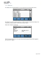
Page 160: ...1007 1 PN1008 1 PN1008 1 DOWN UP By clicking on one of the microphone devices the OPT will start a microphone test beep in the microphone and when passed the MIC test will indicate Passed Select each...

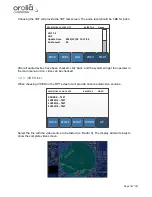
Page 161: ...been checked click back and the system will get the operator in the main menu and i e video can be checked 1 2 3 VIDEO test When choosing VIDEO on the OPT screen it will provide all connected video s...

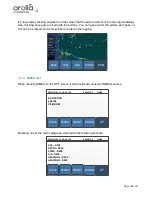
Page 162: ...e recorded in the logging FAIL PASS BACK ZOOM PAN 1 2 4 NMEA test When choosing NMEA on the OPT screen it will provide all connected NMEA sources NIGHT SELECT BACK 2014 12 04 11 18 45 UTC ALERTS 3 NME...

Page 163: ...an be downloaded using the player wizard 1 2 5 OPT log The VDR will log the last 10 Operational Performance Tests which are carried out on the system These logs will be stored on all 3 storage media a...

Page 164: ...test signal on 121 5 and 406 037MHz testing the output of the transmitter While transmitting the test signal the battery voltage output power and phase lock is tested During the test of the 406MHz tr...

Page 165: ...shown Flashes Fault indication 1 NONE 2 Low power on 406 MHz transmitter 3 Low battery voltage 4 Low power on 121 5 MHz transmitter 5 PLL on 406 MHz transmitter out of lock 6 PLL on 121 5 MHz transmit...

Page 166: ...B Module Battery pack If the EPIRB is fitted on a vessel which requires GMDSS compliant equipment the EPIRB shall be serviced tested and approved as required by SOLAS regulation IV 15 9 2 of SOLAS 197...

Page 167: ...e backside of the unit with following meaning Link speed Green LED the LED is on when there is a link connection otherwise the LED is off Activity Yellow LED the LED is flashing when there is activity...

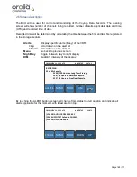
Page 168: ...Down Scroll down on the alert list Menu Go back to previous screen Night Day Toggle between day to night display DIM Backlight intensity of the display NIGHT MENU ALERTS 2014 12 04 11 17 25 UTC ALERTS...

Page 169: ...ion of the VDR In battery backup mode the VDR will continue to operate for 2 hours after which time the VDR will switch off until normal power is restored 2 7 2 Recording Channels NMEA A No data NMEA...

Page 170: ...ecomes unavailable or any data volume has an overflow an ALERT will be generated 2 7 6 Switch A Switch problem with port Indicated port on switch has malfunction 2 7 7 Hardware malfunction A Not activ...

Page 171: ...04 11 17 25 UTC ALERTS 3 LOG CONNECTION PROBLEM CAPSULE 2 14 12 03 10 43 16 till 14 12 03 10 43 18 DOWN UP 2 10 Software version recognition By choosing in the MENU display the SOFTW button will provi...

Page 172: ...11 Screen test The Bridge Control Unit has screen test included By choosing in the MENU display the SCREEN button the display will provide a rectangular black in white figure This will test the corre...

Page 173: ...also take place on an approved free floating Final Recording Medium for a period of not less than 48 hours The unit to be installed in conjunction with this VDR is the Jotron TRON 40VDR which basical...

Page 174: ...ector The HSS has a release mechanism to facilitate underwater recovery both by a diver or a ROV Suitable handles are provided to ensure that the capsule may be retrieved safely after release The HSS...

Page 175: ...ware 5 1Setting up the PC To download a data set from the NW6000 please set your PC to fixed IP address 172 16 8 199 using local area connection network Fill the following IP addresses IP address 172...

Page 176: ...ss of Core Module The Playback software can be downloaded on this page The playback software can be downloaded from www oroliamaritime com login only accessible for service engineers Additional playba...

Page 177: ...in following steps 1 Copy or download file on your laptop or replay device in a folder like in the following screenshot 2 Double click the NetwavePlayerV2_xxx_setup exe xxx number of software release...

Page 178: ...layback a previously stored dataset or alternatively to download a dataset from a storage device which subsequently can be played back using the player Tip The player will start the app by opening a p...

Page 179: ...ding media LTRM FRM and FFRM Upon start up of the Playback application the last stored configuration file applicable for the downloaded dataset will automatically be loaded Although the Playback can b...

Page 180: ...is pressed the Player will search for the previously selected storage device on the VDR network Then the Player will present the time selection for the dataset to be downloaded NOTE The player will a...

Page 181: ...rsed data is stored in a folder cache in the folder selected to download the dataset to Choose the required dataset from long term storage medium in Core Module for download to your computer Give it a...

Page 182: ...te Dataset needs to be available on the computer b Select the dataset to be imported and follow the instructions Note Opening the dataset can take some time depending on the size of the dataset When d...

Page 183: ...START SESSION button This launches the playback but first a user code is required For replay only the default pasword is ocean When logged in with this password only replay is possible Export of data...

Page 184: ...Page 184 191 Figure 5 8 1 Sample dataset playback...

Page 185: ...to another medium for other use To export data from the Player please select page options and press the Export Converted Dataset button When choosing Export Converted Dataset the player wizard will a...

Page 186: ...ast 10 OPT s and complete error log Download from float free and or fixed capsule 7 Playback software details 7 1Passwords There are 2 passwords required to playback data The first password is necessa...

Page 187: ...f the Technical Regulations on the Safety of Sea Transport Items 3 Netwave Systems recommendations for utilization of VDR components according to Interim provisions for the application of the Technica...

Page 188: ...onents according to Russian Federation rules for utilization of such components and paragraph 219 of the Technical Regulations on the Safety of Sea Transport Items VDR PCB controllers can be easily di...

Page 189: ...tabilization on PCB 9 2Power consumption calculation NOTE Below mentioned calculation is given with a three times extra power consumption especially for APP PCB controllers Reason of that to calculate...

Page 190: ...ormity with the Technical Regulations is confirmed shall have a conformity mark as prescribed by the Russian Federation legislation on technical regulation Following components of NW6000 VDR System ar...

Page 191: ...dicated on the BCU see chapter Software version recognition NIGHT STATUS ALERTS 2014 12 04 11 17 40 UTC ALERTS 3 SOFTW BCP SI6000 v 0 6 0 BCU PN5000 v 0 4 17 CAP PN7000 v 0 4 3 MIC PN1006 v 0 9 4 MIC...

Reviews: