Netopia
®
3-D Reach
™
Wi-Fi Gateways
M
M
M
Mo
o
o
od
d
d
dee
e
ellllssss::::
•
•
•
•
Netopia® 3300-Series ADSL 3-D Reach™ Wi-Fi Gateways
•
•
•
•
Netopia® 3300-Series Broadband 3-D Reach™ Wi-Fi Gateways
Quickstart Guide
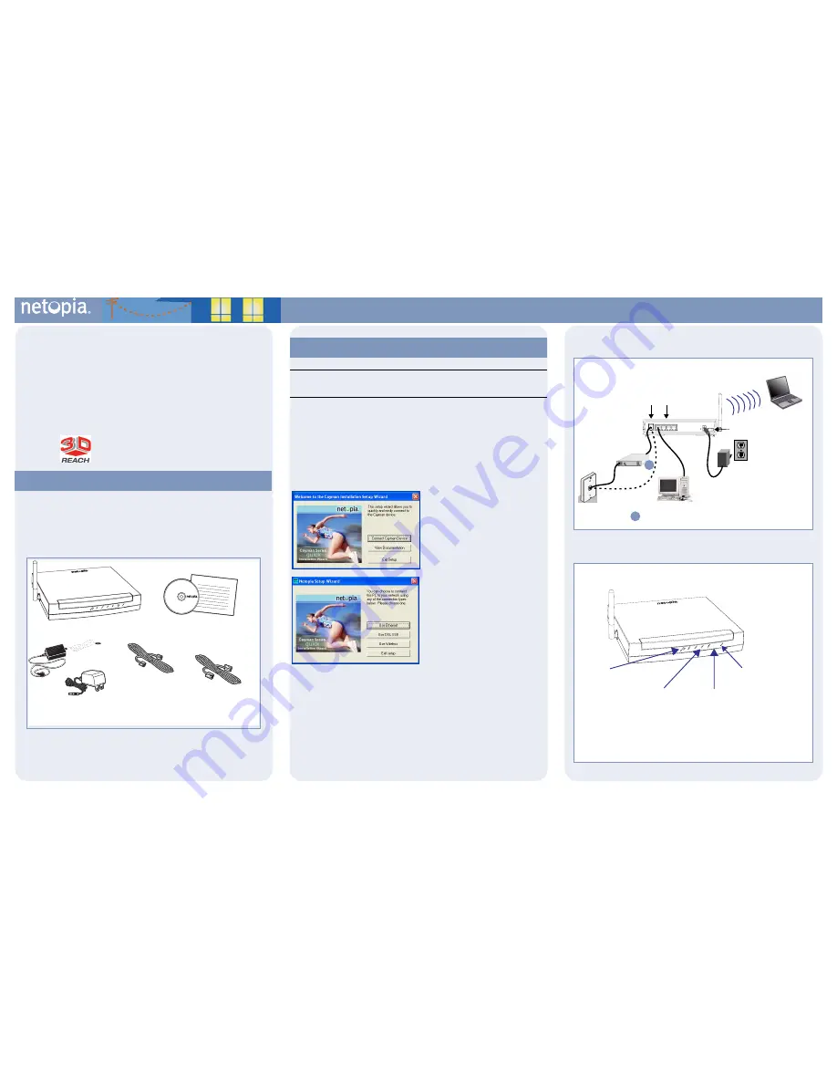
Unpack your Gateway, check your package contents, and decide on a location.
Consider:
•
Place the Gateway in a spot that is easily accessible for you. You can lay it flat or mount
on the wall.
•
Keep the cables away from other electrical devices that may interfere with the operation
of your Gateway.
If you don’t have everything, contact your supplier immediately.
Note:
Note the serial number (
SN:
) of your Gateway. It is located on the label on the bottom of
the Gateway below the model number. You will need the Gateway’s serial number when installing
wireless card(s) or adapters, or if you need to call for technical support.
The Netopia Installation Wizard automates several tasks to get you up and running easily.
You can run the Wizard on every
W
W
W
Wiiiin
n
n
nd
d
d
do
o
o
ow
w
w
wssss----b
b
b
baa
a
assssee
e
ed
d
d
d P
P
P
PC
C
C
C
that will connect to your network,
whether it is connected via Wireless, USB, or by Ethernet cable.
>
>
>
>B
B
B
Bee
e
e ssssu
u
u
urrrree
e
e tttto
o
o
o d
d
d
diiiissssaa
a
ab
b
b
bllllee
e
e ffffiiiirrrree
e
ew
w
w
waa
a
allllllll p
p
p
prrrro
o
o
od
d
d
du
u
u
uccccttttssss ssssu
u
u
ucccch
h
h
h aa
a
assss N
N
N
No
o
o
orrrrtttto
o
o
on
n
n
n P
P
P
Pee
e
errrrsssso
o
o
on
n
n
naa
a
allll FFFFiiiirrrree
e
ew
w
w
waa
a
allllllll o
o
o
orrrr
M
M
M
MccccA
A
A
Affffee
e
eee
e
e P
P
P
Pee
e
errrrsssso
o
o
on
n
n
naa
a
allll FFFFiiiirrrree
e
ew
w
w
waa
a
allllllll b
b
b
bee
e
effffo
o
o
orrrree
e
e rrrru
u
u
un
n
n
nn
n
n
niiiin
n
n
ng
g
g
g tttth
h
h
hee
e
e w
w
w
wiiiizzzzaa
a
arrrrd
d
d
d....<
<
<
<
1.
IIIIn
n
n
nsss
see
e
errrrtttt tttth
h
h
hee
e
e C
C
C
CD
D
D
D iiiin
n
n
ntttto
o
o
o y
y
y
yo
o
o
ou
u
u
urrrr C
C
C
CD
D
D
DR
R
R
RO
O
O
OM
M
M
M d
d
d
drrrriiiivvv
vee
e
e....
The Installation Wizard will run
automatically and step through your connection installation(s).
2.
When prompted, connect a PC to any of the Ethernet “LAN” ports using the
Yellow RJ-45 Ethernet cable.
Use additional standard Category 5 Ethernet cables
(not supplied) to connect up to four devices.
3.
If you are installing a Netopia 3-D Reach Wireless card, use the Netopia
Installation Wizard on your laptop or PC.
If you are using third-party,
non-Netopia-supplied wireless adapters with your Gateway use the drivers/CD
that are compatible for that wireless adapter.
When all of your connections are made, your network may look like this:
When all of your connections are made, the status LEDs on the front of your Netopia Gateway
will light, according to the following diagram:
Checklist
Netopia Gateway
CD & Quickstart Guide
Power
Supply
Lavender RJ-11
Telephone Cable
or
Gray RJ-45
Modem Cable
Yellow RJ-45
Ethernet
Cable
-or-
Use the Netopia Installation Wizard
The Welcome screen lists the tasks that
you can perform with the Netopia Installa-
tion Wizard.
The second screen lets you choose which
type of Netopia device you are installing,
and where you are installing it.
Once you make your choice, subsequent
screens will install the appropriate drivers,
if required, and perform configuration
tasks, depending on the type of device you
are installing.
Follow the on-screen instructions.
Power
Off / On
LAN
Modem
4
1
2
3
DSL or Cable
DC Power
Rear View
Modem
Modem Port
(Ethernet models)
Ethernet
Ports
Power Switch
DSL Port
(DSL models)
1
1
For Ethernet models, connect to DSL or Cable modem;
For DSL models, connect directly to DSL wall outlet
Modem
Power -
Ethernet 1, 2, 3, 4 -
Modem (Ethernet models) -
Flash
green
when there is
activity on the LAN.
Front View
Flashes
green
for activity
on the modem port.
Solid
green
when connected.
Solid
green
when connected.
Green
when power is on.
Wireless -
Flashes
green
when there is
activity on the wireless LAN.
Flashes
green
when training
Solid
green
when trained
DSL Sync (DSL models) -
– OR –
1
2
3
B
ROADBAND
WITHOUT
B
OUNDARIES
™


