Netberg Demos R130 M2 server
14
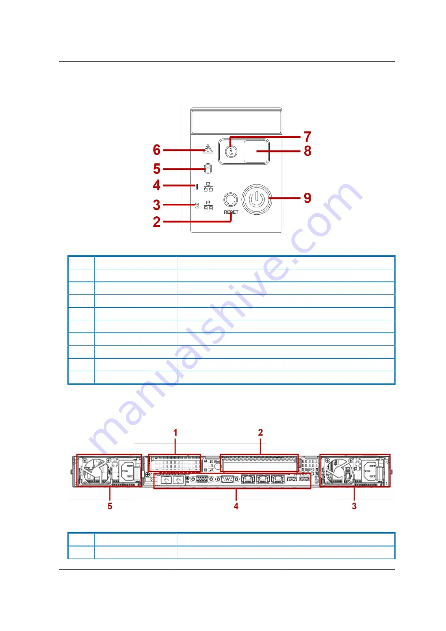
Figure 1.6. 2.5” HDD Front Control Panel
Table 1.4. Front Control Panel Definition
No.
Name
Description
1
USB ports
USB ports 1 & 2
2
Reset button
Soft reset system function
3
LAN2 LED
LAN access
4
LAN1 LED
LAN access
5
HDD activity LED
Hard disk drive access
6
Fault LED
Provides critical and non-critical failure notification
7
Identification LED
Activate ID LED to identify system
8
ID button
Toggles ID LED
9
Power button
Power on/off
1.5.6. System Rear View
Figure 1.7. System Rear View
Table 1.5. System Rear View
No.
Name
Description
1, 2
Expansion slot
PCIe expansion slot with PCIe x8 signal
Summary of Contents for Demos R130 M2
Page 1: ...Netberg Demos R130 M2 server...
Page 2: ...Netberg Demos R130 M2 server...
Page 11: ...Netberg Demos R130 M2 server xi 9 5 Aligning the Rails 222...
Page 14: ...1 Chapter 1 Netberg Demos R130 M2 server...
Page 31: ...Netberg Demos R130 M2 server 18 On HDD failure HDD Fault Amber Off No failure detected...
Page 32: ...19 Chapter 2 Installing hardware...
Page 57: ...Installing hardware 44 Figure 2 36 Installing the Air Duct...
Page 60: ...Installing hardware 47 Figure 2 40 Connecting the Fan Assembly Cables...
Page 143: ...130 Chapter 6 Server Management Software...
Page 169: ...156 Chapter 8 Web Graphical User Interface GUI for ESMS...
Page 230: ...217 Chapter 9 Rail Kit Assembly...
Page 236: ...223 Chapter 10 Troubleshooting...


