
N58 Hardware User Guide
Chapter 5 Application Interfaces
Copyright © Neoway Technology Co., Ltd. All rights reserved.
64
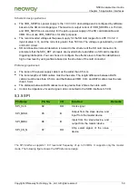
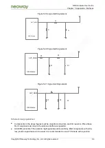
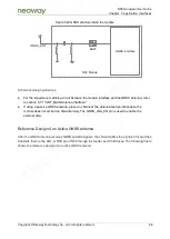
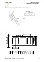
Figure 5-39 L-type matching network
ANT_MAIN
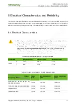
N58 Module
Z1
Z2
D1
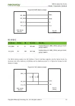
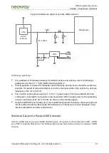
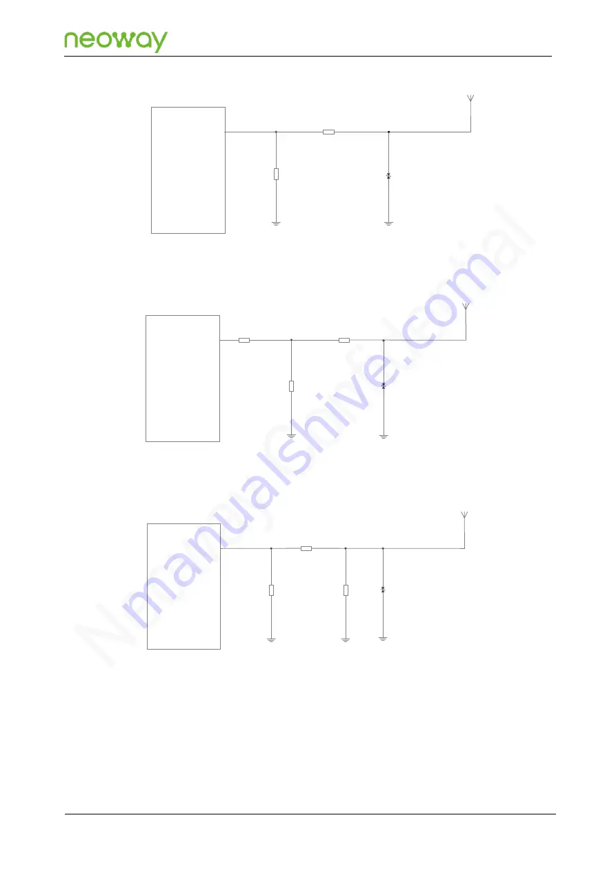
Figure 5-40 T-type matching network
ANT_MAIN
N58 Module
Z1
Z2
D1
Z3
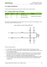
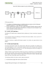
Figure 5-41
π-type matching network
ANT_MAIN
N58 Module
Z1
Z2
D1
Z3
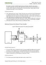
Schematic design guidelines:
Components in the above figures must be capacitors, inductors, and 0 Ω resistors. Place these
RLC components as close to the antenna interface as possible.
Add ESD protection if the antenna might generate static electricity. ESD components with ultra-
low junction capacitance can be used. It is recommended to use a TVS diode with a junction


