


Tucker GmbH,
Mail / Post:
Max-Eyth-Str.1, 35394 Gießen, Germany
Stud welding unit N800i
As of 24.08.2021
Manual part number: BE 1227
28
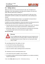
4.
Connection and Installation
4.1 Installation Precautions
Attention must be paid to the fact that the welding unit is installed on horizontal,
vibration
‐
free and non
‐
slip floor space The load
‐
carrying capacity of the floor space
should be at least double the weight of the welding unit.
When working in high
‐
lying locations, such as bridges, ladders or plat
‐
forms the N800i
must be secured against the risk of falling.
The electrical and pneumatic connection lines should be installed as far as possible
without loops
The Nelweld N800i must be adequately protected against the intrusion of liquids. It
may not be installed on liquid
‐
bearing pipelines.
In order to guarantee unimpeded temperature exchange with the environment, a
minimum clearance of 1 m to existing heat sources must be observed.
Attention must be paid to the fact that the ventilation slits on the unit casing are kept
free.
4.2 Connection
With the exception of the mains cable all the connecting elements are arranged in a
functional manner on the front plate of the N800i.
The mains cable with CEE plug is to be found at the rear of the unit.
Warning!
Prior to connecting the N800i to the mains voltage supply, the safety
advice and information in chapter 4.2.1 must be observed!
Summary of Contents for N800iTM
Page 18: ......