Performance Verification
12
Note
:
In addition to serving as the POST pass verification, the POST pass
tone also functions as an audible confirmation that the speaker is
performing properly. If the speaker does not function, the alarm
sounds cannot be heard.
Power-On Defaults and Alarm Limit Ranges
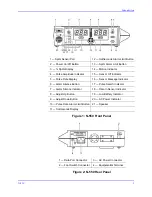
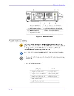
See Figure 3 on page 9 for the location of the N-550 controls.
Note
:
When observing or changing default limits, a three-second time-out is
in effect. That is, if no action is taken within three seconds, the N-550
automatically returns to the normal mode.
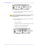
1. Turn the N-550 on by pressing the Power On/Off button.
2. Wait for POST to be completed.
3. Press and release the SpO
2
Alarm Limit button.
4. Verify that the N-550 emits a single beep and the %SpO
2
display indicates
an upper alarm limit of “100” for about three seconds.
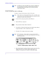
5. Verify that “HI” is displayed in the pulse rate display.
Note
:
“HI” in the display window indicates an upper alarm limit that is
being adjusted, and a “LO” in the window indicates that a low alarm
limit is being adjusted.
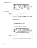
Figure 4: Adjusting High %SpO
2
Alarm Limit
6. Press the SpO
2
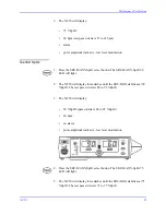
Alarm Limit button. Within 3 seconds, press and hold the
Adjust Down button. Verify that the %SpO
2
display reduces to a
minimum of one point above the %SpO
2
low alarm limits setting.
Summary of Contents for OxiMax N-550
Page 1: ...N 550 Pulse Oximeter Service Manual min min SpO2 N 550 SatSeconds SpO2 ...
Page 10: ...Blank Page ...
Page 38: ...Blank Page ...
Page 64: ...Blank Page ...
Page 81: ...Disassembly Guide N 550 71 Figure 39 Equipotential Ground Terminal Removed ...
Page 82: ...Blank Page ...
Page 86: ...Spare Parts 76 Figure 40 Exploded View ...
Page 90: ...Blank Page ...
Page 108: ...Blank Page ...
Page 120: ...Blank Page ...
Page 130: ...Figure 56 Main PCB Parts Locator Diagram 129 Technical Description N 550 ...
Page 131: ...Figure 57 Front Panel Parts Locator Diagram 131 N 550 Technical Description ...
Page 136: ...Blank Page ...
Page 137: ... ...


