background image

Rail System 920 Touchless

EN

For technical advice about installation, contact

Nederman.

4.5 Install rail sections and fan

For installing the rail system and connecting the trol-

ley, see the manual, Mounting instructions, rail.

4.6 Telescopic pipe

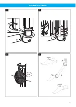
See 

Figure 4

. Fit the jointed arm together with the

nozzle to the telescopic pipe.

2 Screw two screws all the way in, until stop

(without using force), and then loosen half a turn.

CAUTION! Risk of equipment damage

Do not force the screws, they may break.

See 

Figure 5

. Fit the lever according to (A) and (B).

Compress all sections of the telescopic pipe to the

stop position and fasten the screw. The support

ring above the jointed arm must rest on the top

flange of the lever in order to keep the telescopic

pipe in place.

4.7 Installation checklist

When the mechanical assembly and fan connection

of the system are complete, it is ready for use after

double-checking the following points.
1 Check the airflow in the nozzle opening with an

airflow indicator.

2 Check that there is enough suction capacity in

the extraction unit before it is connected to the

vehicle’s exhaust pipe. If not, check the fan im-

peller rotation direction and/or damper function.

If necessary check the installation of the fan start

switch.

3 Check the telescopic function. When required,

adjust the balancer lifting power. See 

Sec-

tion 4.8 Adjusting the lifting power of the balan-

cer

.

4 Check that the suction trolley can easily be moved

in the rail.

4.8 Adjusting the lifting power of the

balancer

See 

Figure 6

.

4.8.1 Increasing the lifting power

Hold the knurled wheel (A) of the balancer drum in a

steady grip and turn the balancer drum (B) clockwise

for increased lifting power.

4.8.2 Reducing the lifting power

1 Pull a little cord from the balancer drum.
2 Hold the balancer drum (B) in a steady grip and re-

move one or two revolutions of the cord.

5 Operation

The system is designed for use only with sta-

tionary vehicles. The vehicle must not be

moved when the nozzle has been placed next

to the vehicle exhaust pipe.

Use two hands when moving the nozzle and

arm.

See 

Figure 7

. Press down the blue button (1) on top of

the nozzle. Move the arm and nozzle into position and

then release the blue button. The joints (2) are now

locked into place.
See 

Figure 8

. The extraction unit is equipped with a

mechanical damper. The damper is closed when the

lever on the top section of the extraction unit is pulled

out and the telescopic unit is moved up to the parking

position (A). There is a stop (B) on the lever to prevent

unintentional from shutting off of the damper func-

tion. Pull out the lever to pull down the telescopic unit.

The telescopic unit is balanced and will stay in the po-

sition where it is left.
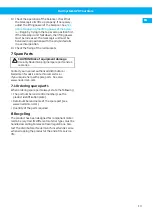
Check the positioning of the nozzle to make sure it is

properly positioned. The nozzle shall be placed a bit

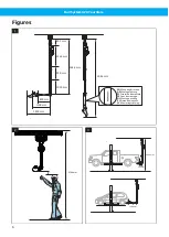
behind the vehicle exhaust pipe. See 

Figure 9

Fig-

ure 10

 and 

Figure 11

.

6 Maintenance

CAUTION! Risk of equipment damage

Use only N

$

e

$

d

$

e

$

r

$

m

$

a

$

n

$

 original spare parts and ac-

cessories.

Check the following points, regarding fixing, function-

ing or wear, at periodic intervals but at least annually

or when replacing 

parts.

1 Rail
2 The trolley stop.
3 The wheels of the suction trolley.
4 Check that the suction trolley moves easily in the

whole length of the rail.

5 Check the guideway of the suction trolley regard-

ing wear. Clean the guideway if necessary.

6 Check the rubber buffer of the suction trolley.
7 Check that there are no cracks around the wheel

carriers of the suction trolley.

8 The nozzle
9 Check that there is enough suction power in the

nozzle.

10 Check the damper function.
11 Check the telescopic function with regard to bal-

ancing, noise, and friction.

12 The cord on the balancer at least once every 6

months. See 

Section 4.8 Adjusting the lifting

power of the balancer

.

12

Summary of Contents for SYSTEM 920

Page 1: ...uchless Original user manual EN USER MANUAL Translation of original user manual DE BEDIENUNGSANLEITUNG ES MANUAL DE USUARIO FR MANUEL DE L UTILISATEUR NL GEBRUIKERSHANDLEIDING PL INSTRUKCJA OBS UGI SV...

Page 2: ...Rail System 920 Touchless Trace back information Workspace Main version a11 Checked in 2020 09 08 Skribenta version 5 3 081...

Page 3: ...Rail System 920 Touchless Declaration of conformity 4 Figures 6 English 9 Deutch 14 Espa ol 19 Fran ais 24 Nederlands 29 Polski 34 Svenska 39 3...

Page 4: ...bre y firma que figuran al final de este documento corresponden a la persona responsable tanto de la declaraci n como de la ficha t cni ca FR Fran ais D claration de conformit Nous AB Ph Nederman Co d...

Page 5: ...on avser r i verensst mmelse med alla re levanta best mmelser i f ljande direktiv och standarder Direktiv 2006 42 EC Standarder EN ISO 12100 Namnet och signaturen i slutet av detta dokument r den pers...

Page 6: ...30 mm 950 mm 1265 mm 3646 mm 401 mm 5046 mm 1100 mm 800 mm EN Moun ng direc on ES Direcci n de montaje NL Montage rich ng FR Sens de montage DE Montagerichtung PL Kierunek monta u SV Monteringsriktnin...

Page 7: ...Rail System 920 Touchless 4 A B 5 A B Klick 6 2 2 1 7 7...

Page 8: ...Rail System 920 Touchless A B 8 9 10 11 8...

Page 9: ...3 2 Technical data 11 4 Installation 11 4 1 Delivery check 11 4 2 Rail placement 11 4 3 Vertical placement 11 4 4 Horizontal placement 11 4 5 Install rail sections and fan 12 4 6 Telescopic pipe 12 4...

Page 10: ...either as a warning caution or note ac cording to the following examples WARNING Risk of personal injury Warnings indicate a potential hazard to the health and safety of personnel and how that hazard...

Page 11: ...e used with the unit See Figure 3 Figure 9 Fig ure 10 and Figure 11 4 3 Vertical placement See Figure 2 The mounting height from the top of the rail to the floor is 4100 mm This height allows enough f...

Page 12: ...steady grip and re move one or two revolutions of the cord 5 Operation The system is designed for use only with sta tionary vehicles The vehicle must not be moved when the nozzle has been placed next...

Page 13: ...original spare parts and ac cessories Contact your nearest authorized distributor or N e d e r m a n for advice on technical service or if you require help with spare parts See also w w w n e d e r m...

Page 14: ...Technische Daten 16 4 Installation 16 4 1 Kontrolle der angelieferten Ware 16 4 2 Anordnung der Schiene 16 4 3 Vertikale Platzierung 16 4 4 Horizontale Platzierung 16 4 5 Installation von Schienensekt...

Page 15: ...e se hen Sie hierzu folgende Beispiele WARNUNG Verletzungsgefahr Warnungen weisen auf eine m gliche Gefahr f r die Gesundheit und die Sicherheit der Be nutzer sowie auf die Gefahrenvermeidung hin VORS...

Page 16: ...hne Es ist sehr wichtig zu entscheiden welche Fahrzeugl ngen mit dem Ger t verwendet werden sollen Siehe Abbildung 3 Abbildung 9 Abbil dung 10 und Abbildung 11 4 3 Vertikale Platzierung Siehe Abbildu...

Page 17: ...npassen der Hubkraft des Balancers 4 Sicherstellen dass der Absaugwagen leichtg ngig auf der Schiene ist 4 8 Anpassen der Hubkraft des Balan cers Siehe Abbildung 6 4 8 1 Erh hen der Hubkraft Das R nde...

Page 18: ...en mit dem Ge lenkarm in senkrechter Stellung im Gleichgewicht sein 14 Befestigung der Schienenhalter kontrollieren 7 Ersatzteile VORSICHT Gefahr der Anlagenbesch di gung Verwenden Sie ausschlie lich...

Page 19: ...4 1 Comprobaci n a la entrega 21 4 2 Colocaci n del ra l 21 4 3 Colocaci n vertical 21 4 4 Colocaci n horizontal 21 4 5 Instalaci n de las secciones del ra l y el aspirador 22 4 6 Tubo telesc pico 22...

Page 20: ...ejemplos ADVERTENCIA Riesgo de lesiones perso nales Las advertencias indican un peligro potencial para la salud y la seguridad del personal y la forma en que el peligro puede ser evitado PRECAUCI N R...

Page 21: ...al representante local de Nederman 4 2 Colocaci n del ra l Antes de montar el equipo determine la altura y la po sici n del ra l en relaci n con el elevador del coche Es muy importante decidir qu long...

Page 22: ...a v lvula Si es necesario com pruebe la instalaci n del interruptor de encendido del ventilador 3 Compruebe el mecanismo telesc pico Cuando sea necesario ajuste la fuerza de elevaci n del equili brado...

Page 23: ...n supe rior o cero en primer lugar Si la unidad telesc pica se cae se debe aumentar la fuerza de elevaci n La unidad telesc pica debe estar equilibrada en todas las posiciones con el brazo articulado...

Page 24: ...stallation 26 4 1 V rification de la livraison 26 4 2 Emplacement du rail 26 4 3 Placement vertical 26 4 4 Placement horizontal 26 4 5 Installation des sections du rail et du ventilateur 27 4 6 Tube t...

Page 25: ...NTION Risque de blessure Les avertissements indiquent un danger po tentiel li la sant et la s curit du person nel et expliquent comment ce danger peut tre vit ATTENTION Risque de dommages sur l quipem...

Page 26: ...ail Avant de monter le produit d terminer la hauteur et la position du rail par rapport au pont l vateur Il est essentiel de d cider des longueurs de v hicule utili ser avec l appareil Voir Figure 3 F...

Page 27: ...libreur 4 V rifier que le chariot d aspiration peut facilement tre d plac sur le rail 4 8 R glage de la puissance de levage de l quilibreur Voir Figure 6 4 8 1 Augmentation de la force de levage Tenir...

Page 28: ...e dans toutes les positions avec le bras articul dans une position verticale 14 V rifier la fixation des supports du rail 7 Pi ces de rechange ATTENTION Risque de dommages sur l quipement Utiliser uni...

Page 29: ...3 2 Technische gegevens 31 4 Installatie 31 4 1 Controle bij levering 31 4 2 Plaatsing rail 31 4 3 Verticale plaatsing 31 4 4 Horizontale plaatsing 31 4 5 Installatie van railsecties en ventilator 32...

Page 30: ...voorgesteld Zie de volgende voorbeelden WAARSCHUWING Gevaar voor persoonlijk letsel Waarschuwingen wijzen op een mogelijk ge vaar voor de gezondheid en veiligheid van het personeel en hoe dat gevaar k...

Page 31: ...u de hoog te en positie van de rail ten opzichte van de plaats van de auto bepalen Het is zeer belangrijk om te beslissen voor welke voertuiglengtes het product gebruikt gaat worden Zie Afbeelding 3...

Page 32: ...het afzuigwagentje makkelijk in de rails loopt 4 8 Trekkracht van de lifter instellen Zie Afbeelding 6 4 8 1 Trekkracht verhogen Houd de geribbelde knop A van de liftertrommel ste vig vast en draai de...

Page 33: ...14 Controleer de bevestigingen van de railklemmen 7 Reserveonderdelen VOORZICHTIG Gevaar voor schade aan het materieel Gebruik uitsluitend originele reserveonderde len en accessoires van N e d e r m a...

Page 34: ...niczne 36 4 Monta 36 4 1 Kontrola dostawy 36 4 2 Usytuowanie szyny 36 4 3 Umieszczenie pionowe 36 4 4 Poziome umieszczenie 36 4 5 Instalacja segment w szyny i wentylatora 37 4 6 Rura teleskopowa 37 4...

Page 35: ...ne informacje przed stawione w postaci ostrze e przestr g lub uwag Oto ich przyk ady OSTRZE ENIE Niebezpiecze stwo odnie sienia obra e Ostrze enia wskazuj na potencjalne zagro enia dla zdrowia i bezpi...

Page 36: ...2 Usytuowanie szyny Przed zamontowaniem produktu nale y okre li wy soko i po o enie szyny w stosunku do podno nika samochodowego Bardzo wa ne jest aby zdecydo wa jakie d ugo ci pojazdu maj by u ywane...

Page 37: ...si e w zek ssawny przesuwa si swo bodnie w szynie 4 8 Regulacja si y podnosz cej balanse ra Patrz Ilustracja 6 4 8 1 Zwi kszanie si y podnosz cej Aby zwi kszy si podnosz c silnie przytrzymaj mo letowa...

Page 38: ...anie wspornik w szyn 7 Cz ci zamienne PRZESTROGA Ryzyko uszkodzenia sprz tu Nale y u ywa wy cznie oryginalnych cz ci zamiennych firmy N e d e r m a n W razie konieczno ci uzyskania wskaz wek dotycz cy...

Page 39: ...41 3 1 1 M tt 41 3 2 Tekniska data 41 4 Installation 41 4 1 Leveranskontroll 41 4 2 Skenplacering 41 4 3 Vertikal placering 41 4 4 Horisontell placering 41 4 5 Montera skensektioner och fl kt 42 4 6...

Page 40: ...ntingen som en varning ett f rsiktig hetsmeddelande eller en kommentar Se f ljande ex empel VARNING Risk f r personskada Varningar anger en m jlig fara f r personalens h lsa och s kerhet samt hur fara...

Page 41: ...enheten Se Figur 3 Figur 9 Figur 10 och Figur 11 4 3 Vertikal placering Se Figur 2 Monteringsh jden fr n skenans ovansida till golvet r 4100 mm Denna h jd ger tillr ckligt myc ket plats f r att man sk...

Page 42: ...rt ett eller tv varv lina 5 Drift Systemet r avsett f r att anv ndas endast p stillast ende fordon Fordonet f r inte flyttas n r munstycket r anslutet till avgasr ret Flytta munstycket och armen med b...

Page 43: ...service eller om du beh ver best lla reservdelar Se ven w w w n e d e r m a n c o m 7 1 Best lla reservdelar Ange alltid f ljande information vid best llning av re servdelar Komponent och kontrollnumm...

Page 44: ...www nederman com...

Reviews: