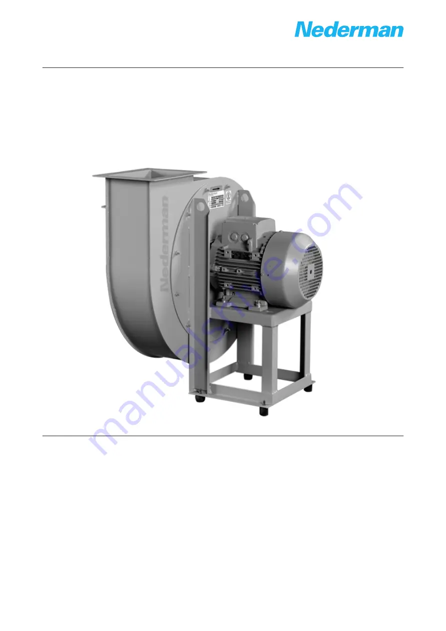
Central Fan
NCF
144042(04)
2018-01-16
Original instruction manual
EN
INSTRUCTION MANUAL
Instruction manual
Page 1: ...Central Fan NCF 144042 04 2018 01 16 Original instruction manual EN INSTRUCTION MANUAL Instruction manual ...
Page 2: ...NCF 2 ...
Page 3: ...NCF 3 Declaration of conformity 4 Figures 5 English 9 ...
Page 4: ...visions of the following directives and standards Directives 2006 42 EC 2014 30 EU Standards SS EN ISO 12100 The name and signature at the end of this document is the person responsible for both the declaration of conformity and the technical file English EN 14550128 14550328 14550728 14550828 14550928 14551028 14551228 14551328 14551428 14551528 AB Ph Nederman Co P O Box 602 SE 251 06 Helsingborg...
Page 5: ...5 U2 U5 V2 V5 U1 V1 W1 U5 W2 V5 U2 V2 W5 W2 W5 U2 U5 V2 V5 YY connection 230 V connection 230 V L1 L2 L3 Y connection 460 V U1 V1 W1 L1 L2 L3 U1 V1 W1 U1 V1 W1 L1 L2 L3 connection 460 V W2 U2 V2 W2 W5 U2 U5 V2 V5 U1 V1 W1 U1 V1 W1 L1 L2 L3 connection 380 V Figures 1 2 MOUNTING INSTRUCTION Vibration absorber 3 ...
Page 6: ...NCF 6 4 Standard outlet position 5 ...
Page 7: ...NCF 7 Example of lifting NCF fans Minimum installation distances with intake pipe 6 7 ...
Page 8: ...NCF 8 Minimum installation distances with open intake Delta connection with a single speed motor 8 9 Star connection for single speed motor 10 ...
Page 9: ...ormation 16 4 2 1 Fan orientation 16 4 2 2 Standard fan outlet position for NCF fans 16 4 3 Transport and installation 16 4 3 1 Transport and lifting 16 4 3 2 Storage in a warehouse 17 4 3 3 Lifting NCF fans 17 4 4 Installation 17 4 4 1 Minimum distances between components 18 4 4 2 Connections to pipes 18 4 4 3 Electrical connections 18 4 4 4 Delta connections 18 4 4 5 Star connections 18 4 5 Chec...
Page 10: ...of personnel and how that hazard may be avoided CAUTION Risk of equipment damage Cautions indicate a potential hazard to the product but not to personnel and how that hazard may be avoided NOTE Notes contain other information that is important for personnel 2 1 Installation WARNING Risk of personal injury The safety measures adopted for using the fan must also be tailored to suit the specific appl...
Page 11: ...ch must always be carried out in conditions of the utmost safety with the fan separated from the motor or isolated using suitable equipment Once the installer and or user has decided which installation type is to be used and all the above procedures have been applied the machine can now be considered a complete machine as described by machine use regulations An overall risk evaluation must be made...
Page 12: ...two moving parts for example between a belt and a pulley Suction of a part of the body into the fan and subsequent contact with the shaft or rotor Contact with a moving part such as the rotor An object becoming sucked into the intake of the fan and expelled at high speed from the outlet of the fan Contact with surfaces of the fan at dangerous temperatures for example temperatures below 20 C or abo...
Page 13: ... induced by another fan installed elsewhere in the connected tubing system This can also lead to parts of the body becoming trapped and seriously injured between the rotor itself and fixed parts of the fan housing A fan maintenance program must be drawn up and followed to prevent the mechanical failure or breakage due to wear or insufficient maintenance 3 Description 3 1 Technical specifications 3...
Page 14: ...540 870 3640 1320 4540 1570 3170 1020 3590 1170 5260 1700 5060 1870 Motor power kW 2 2 3 0 4 0 5 5 5 5 7 5 11 15 18 5 Speed r min 3500 3515 3535 3510 3520 3550 3540 3550 3560 Voltage V Current A 208 8 6 208 11 5 208 15 1 208 18 7 208 18 7 208 26 2 208 38 4 208 52 208 66 4 Voltage V Current A 230YY 460Y 7 8 3 9 230YY 460Y 10 4 5 2 230 460 13 6 6 8 230 460 17 8 5 230 460 17 8 5 230 460 23 8 11 9 230...
Page 15: ...12 150 232 292 Working temperature C Maximum 60 Maximum 60 Maximum 60 Maximum 60 Maximum 60 Maximum 60 Ambient temperature C 30 to 40 30 to 40 30 to 40 30 to 40 30 to 40 30 to 40 See Figure 2 3 1 4 Technical data 60 Hz fans imperial Table 3 4 Technical data 60 Hz fans imperial NCF 30 15 NCF 30 20 NCF 30 25 NCF 40 25 NCF 50 25 NCF 80 20 NCF 120 15 NCF 120 25 NCF 160 25 Capacity cfm 315 2466 410 254...
Page 16: ...tify the carrier and the local Nederman representative immediately 4 2 General information 4 2 1 Fan orientation NCF fans can be built in 14 different orientations The orientation of a fan is expressed as seen from the transmission side See Figure 4 4 2 2 Standard fan outlet position for NCF fans The standard NCF fans are delivered as RD0 shown in Figure 5 Other positions can be delivered on reque...
Page 17: ...nce every possible configuration for lifting a NCF fan 4 3 3 Lifting NCF fans NCF fans are equipped with a motor When lifting these fans as well as using the specific holes in fan structure the eyebolt for lifting the motor must also be used as shown in Figure 6 4 4 Installation The fan does not require the preparation of a special machine bed for its installation A well leveled concrete surface t...
Page 18: ...entire electrical system up to motor terminal board We remind you of the importance of installing a safe connection to earth for the fan The earth connection system must comply with legislation in effect in the country of installation and must be periodically checked by qualified personnel Make the connection to earth before any other connection Check that the connection layout is suited to the ma...
Page 19: ...be carried out with the fan running Check that the power absorption does not exceed the value indicated on the motor identification plate if it does stop the fan immediately and contact the manufacturer The fan must run without excessive vibration and noise Check with the fan at rest and at an outside air temperature of 20 C that the bearings do not exceed the maximum operating temperature maximum...
Page 20: ...y components Intrinsic fault in the bearings Malfunction of the bearings due to unbalanced rotor Excessive noise Contact between moving and stationary components Fluctuating fan operation Electromagnetic fault in motor Orifices or sharp angles in tubing 5 Maintenance CAUTION Risk of equipment damage Use only Nederman original spare parts and accessories Read Chapter 2 Safety before carrying out ma...
Page 21: ...ried out with the following conditions You must be absolutely certain that the fan is completely stationary fan rotor at rest disconnect the electrical power at the main panel with the switch lock the switch with a padlock and hand the key to the head of maintenance The working environment must be equipped with every tool necessary and must be free of any hazards Every piece to be refitted must be...
Page 22: ...ques M for bolts with ISO metric thread d x pitch mm S r mm 8 8 M Nm 10 9 M Nm 12 9 M Nm 6 x 1 20 1 1 10 4 2 15 3 3 17 9 7 x 1 28 9 17 2 25 30 8 x 1 25 36 6 25 37 44 10 x 1 5 58 50 73 86 12 x 1 75 84 3 84 3 127 148 14 x 2 115 115 115 115 16 x 2 157 214 314 368 18 x 2 5 192 306 435 509 20 x 2 5 245 432 615 719 22 x 2 5 303 592 843 987 24 x 3 353 744 1060 1240 27 x 3 459 1100 1570 1840 30 x 3 5 561 ...
Page 23: ...esigned for component materials to be recycled Its different material types must be handled according to relevant local regulations Contact the distributor or Nederman if uncertainties arise when scrapping the product at the end of its service life ...
Page 24: ......
Page 25: ...www nederman com ...