background image

Data Assignment

Chapter 4

INITIAL SETUP

75

Setup Data Assignment Using CLI

This section describes data assignment for WL Controller and WL Access Points 

by using Command Line Interface (CLI).

Before Doing This Task

When you perform data assignment using CLI, the following information are 

required:

l

IP address and subnet mask for a WL Controller

l

Default Gateway’s IP address and subnet mask

l

RADIUS Server’s IP address

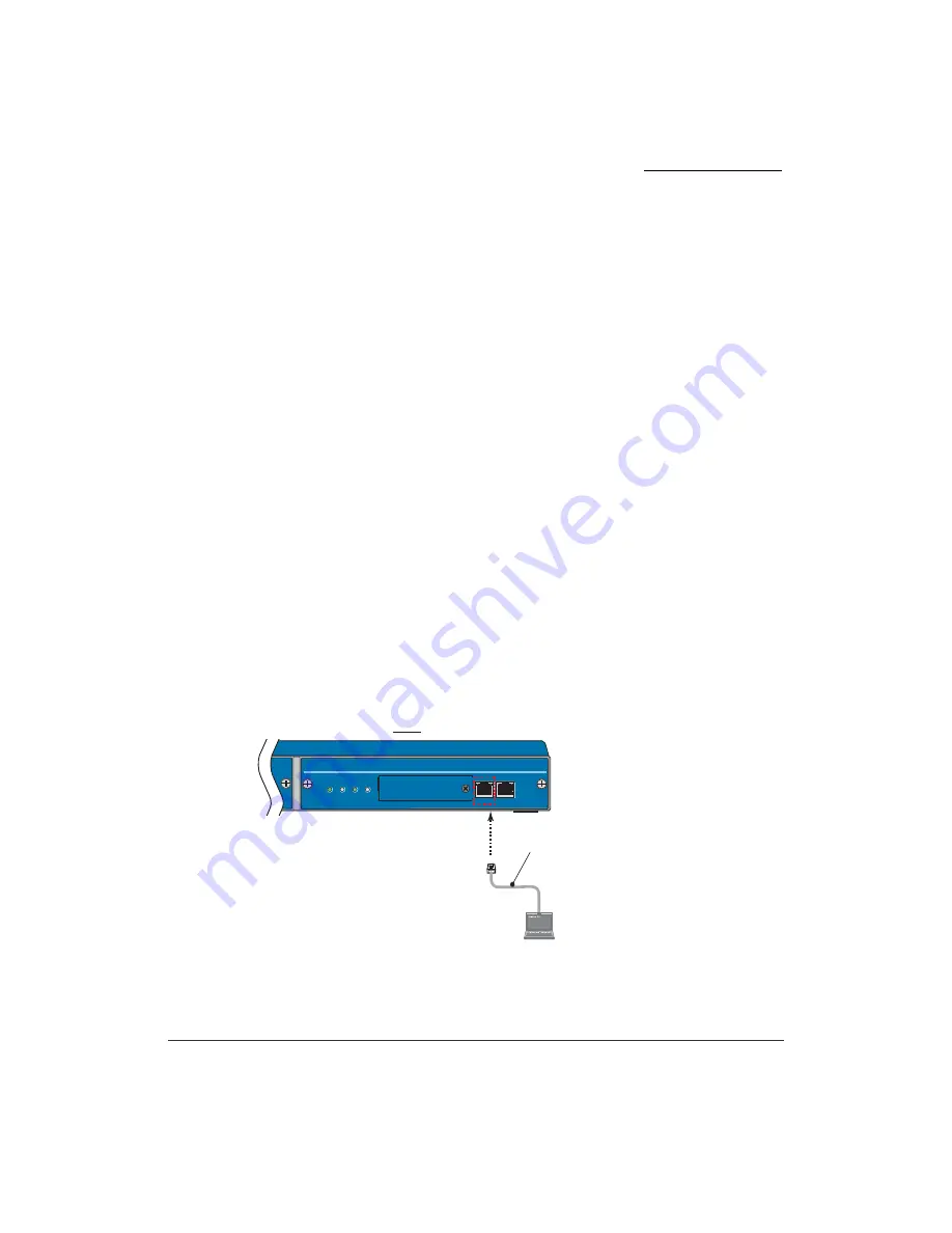
Besides, PC and WL Controller must be connected directly. The following are 

network settings at initial state.

IP address: 192.168.100.10

Subnet address: 255.255.255.0

Assign the appropriate network settings to PC. And then use a cross-over cable to 

connect them. 

The following is an example when PC is connected to SCA-WL10. WL5100 is 

also connected through Ether 1 connector.

10BASE-T/100BASE-TX

Cross-over Cable

Setup PC

Ether1

100M   LINK

100M   LINK

Ether2

PWR

ACT

ALM

LOAD

Front

Example of Network Settings

IP Address

192.168.100.11

Subnet Mask

255.255.255.0

Summary of Contents for WL1700-MS

Page 1: ...V1 WL1700 MS Installation Guide NWA 027515 001 ISSUE 1 0 ...

Page 2: ...yees and customers The information contained herein is the property of NEC Infrontia Corporation and shall not be reproduced without prior written approval from NEC Infrontia Corporation All brand names and product names on this document are trade marks or registered trademarks of their respective companies For more information about trademarks and service marks refer to here Copyright 2007 NEC In...

Page 3: ... or presented upon purchase of this product The correspondence of product name and model type which indicate the same equipment is listed below In this manual product names will be used to indicate each equipment Product Name Model Type WL5100 SN8149 WLCEB A WL1500 AP SN8146 WLAPEA A WL1700 MS SN8147 WLAPEB A ...

Page 4: ...eement between you regardless of whether you are individual or entity and NEC i regarding the software defined below hereinafter referred to as Licensed Program The Licensed Program is preinstalled in the UNIVERGE WL Controller hereinafter referred to as Product Once you use the Licensed Program it is deemed that you have agreed to the terms and conditions of this Agreement If you do not agree to ...

Page 5: ... 2 to make only one copy of the Licensed Program to elective devices or media only for its back up purposes Rights and Restrictions l No reverse engineering decompiling and disassembling You are not allowed to reverse engineer decompile or disassemble the Licensed Program l Prohibition of separating the Licensed Program Because the Licensed Program is part of this Product indivisibly you are not a...

Page 6: ...ill be performed by NEC i in accordance with the support and maintenance agreement if NEC i and you agree to the terms and conditions thereof separately IN NO EVENT SHALL NEC I AND ITS DISTRIBUTORS BE LIABLE TO YOU FOR INDIRECT SPECIAL INCIDENTAL CONSEQUENTIAL OR PUNITIVE DAMAGES INCLUDING LOSS OF PROFITS WHETHER BASED ON CONTRACT TORT OR ANY OTHER LEGAL THEORY AND EVEN IF ADVISED OF THE POSSIBILI...

Page 7: ...gram for purposes related to arms manufacture Moreover you shall not provide or allow to use any third person intending to use the Licensed Program for weapon or arms manufacture with all or any part of the Licensed Program and technologies used in design and usage of this program in any manner or in any condition This Agreement is governed and construed by the laws of Japan If there is any questi...

Page 8: ...l Software License Agreement for This Product l Registered Trademarks and Service marks Discarding the Model When discarding the UNIVERGE WL Wireless Controllers and the UNIVERGE WL Access Points follow the procedure in compliance with the regulations of the local government For more information contact the local government Consumables Some parts in our Product such as cooling fan and internal bat...

Page 9: ...e overseas Use in Medical Institutions This device is not intended to affect human life and provide high degree of reliability Using medical device nuclear facility or equipment aero space equipment and transport equipment is not intended NEC Infrontia Corporation assumes no responsibility for injury or death fire accident or social harm as a result of using the Product for above purposes For your...

Page 10: ...sonal injury or a serious system fault DANGER Incorrect use of the equipment may cause personal injury or death The following safety information describes how to prevent danger and damage to your properties ٟSafety Symbol Learn the meaning of the following symbols and then read this section carefully before using the equipment Do not plug too many leads into a single socket using branched plug soc...

Page 11: ... and equipment failure If condensation occurs unplug the cord and dry naturally or use after letting the equipment adjust to the temperature Do not place the Product where there is movement shock or inclination When placing at Access Points or ceilings use the enclosed tools and check regularly to see if the placement is secure Otherwise the Product will fall and may result in fire electric shock ...

Page 12: ...oduct cover There are high voltage parts inside which may cause electric shock It may also result in fire and equipment failure Contact the distributor for cleaning and repairing the Product Do not use option boards and equipment other than the ones specified It may result in fire electric shock and equipment failure To prevent those from occurring take the following When turning on electricity fo...

Page 13: ...o Part 15 of the FCC Rules These limits are designed to provide reasonable protection against harmful interference when the equipment is operated in a residential environment This accepted equipment is designed and tested to provide reasonable protection against harmful interference when the equipment is operated in a commercial environment This equipment generates uses and can radiate radio frequ...

Page 14: ...nterference Causing Equipment Regulation RSS 210 Cet appareil respecte les exigences du Reglement sur le material broilleur du Canada This device complies with the limits of Industry Canada IC Operation is subject to the following conditions l This device may not cause harmful interference l This device must accept any interference received including interference that may cause undesired operation...

Page 15: ... requirements and other relevant provisions of Directive 1999 5 EC http www nec philips com doc Electromagnetic Compatibility For WLAN controller WL5100 the following warning is applicable Warning This is a class A product In a domestic environment this product may cause radio interference in which case the user may be required to take adequate measures ...

Page 16: ...FCC Rules These limits are designed to provide reasonable protection against harmful interference when the equipment is operated in a residential environment This accepted equipment is designed and tested to provide reasonable protection against harmful interference when the equipment is operated in a commercial environment This equipment generates uses and can radiate radio frequency energy and i...

Page 17: ...gnetic wave laws This equipment operates in the same frequency bandwidth as industrial scientific and medical devices such as microwave ovens and mobile object identification RF ID systems licensed premises radio stations and unlicensed specified low power radio stations used in factory production lines 1 Before using this equipment make sure that no premises radio stations or specified low power ...

Page 18: ...measures the following problems may arise l Transmitted data may be seen A malicious intruder may purposely intercept the radio waves E mails with personal information such as ID password or credit card number may be seen l Possibility of intrusion 1 2 4 Indication of radio equipment using 2 4GHz 2 DS OF Indicates DS SS method Indicates OFDM method 3 4 Indicates assumed interference distance towar...

Page 19: ...stered for the wireless LAN device Thus to lessen the possibility of security problems to occur please complete all security settings for wireless LAN in accordance to the manual before using wireless LAN cards and Access Points Please use this product upon understanding that due to the nature of wireless LAN it is possible for security settings to be broken by unusual methods If you have difficul...

Page 20: ...try code Under no circumstances should you specify a country code that does not match the country of operation If the software does not support the country of operation this might be because the country has not yet approved the use of this equipment In this case contact your local supplier before installing the equipment The WL1500 Access Point was not designed for installation and use in an outdo...

Page 21: ... made with your supplier please contact the local authorities for further information The symbol depicted here has been affixed to your product in order to inform you that electrical and electronic products should not be disposed of as municipal waste Electrical and electronic products including the cables plugs and accessories should be disposed of separately in order to allow proper treatment re...

Page 22: ...tory Notices for Taiwan 低功率電波輻射性電機管理法 第十四條 經型式認證合格之低功率射頻電機 非經許可 公司 商號或使用者均 不得擅自變更頻率 加大功率或變更原設計之特性及功能 第十七條 低功率射頻電機之使用不得影響飛航安全及干擾合法通信 經發現有干擾現象時 應立即停用 並改善至無干擾時方得繼續使用 前項合法通信 指依電信法規定作業之無線電通信 低功率射頻電機 須忍受合法通信或工業 科學及醫療用電波輻射性電機設備之干擾 ...

Page 23: ...IRECT INDIRECT INCIDENTAL SPECIAL EXEMPLARY OR CONSEQUENTIAL DAMAGES INCLUDING BUT NOT LIMITED TO PROCUREMENT OF SUBSTITUTE GOODS OR SERVICES LOSS OF USE DATA OR PROFITS OR BUSINESS INTERRUPTION HOWEVER CAUSED AND ON ANY THEORY OF LIABILITY WHETHER IN CONTRACT STRICT LIABILITY OR TORT INCLUDING NEGLIGENCE OR OTHERWISE ARISING IN ANY WAY OUT OF THE USE OF THIS SOFTWARE EVEN IF ADVISED OF THE POSSIB...

Page 24: ...rks and Service Marks UNIVERGETM is trademarks of NEC Infrontia Corporation All other trademarks service marks and product names used in this document are the property of their respective owners In this manual R and TM marks are not used ...

Page 25: ...Mounting Plates 2 Attached on the product Screws for 19 inch Rack Mounting Plate 6 Attached on the product Screws for 19 inch Rack Mounting 4 inch standard item Spring Washers for Screw 4 inch standard item Plain Washers for Screw 4 inch standard item Screws for 19 inch Rack Mounting 4 mm standard item with spring and plain washers WL First Step Guide 1 This describes precaution statement and atta...

Page 26: ...r Clamps 6 Mounting Hardware Screws 2 Mounting Hardware Wall Anchors 2 Rubber Feet 3 For tabletop Installation WL First Step Guide 1 This describes precaution statement and attachment of the package ARIB Sticker 1 Mounting Template UNIVERGE WL Intelligent Access Point Mounting Bracket Wall Anchors Mounting Screws T Bar Clamps Use it with T bar Rubber Feet 1 4 5 6 7 8 2 3 WL First Step Guide Mounti...

Page 27: ...s 6 Mounting Hardware Screws 2 Mounting Hardware Wall Anchors 2 Rubber Feet 3 For tabletop Installation WL First Step Guide 1 This describes precaution statement and attachment of the package ARIB Sticker 1 Mounting Template UNIVERGE WL Access Point Mounting Bracket Wall Anchors Mounting Screws T Bar Clamps Use it with T bar Rubber Feet 1 4 5 6 7 8 2 3 WL First Step Guide Mounting Hardware ARIB St...

Page 28: ...Additional License is necessary when more than 50AP licenses are to be used CONTENTS QUANTITY REMARK UNIVERGE WLMS Software 1 This is a main product software CD R License Sheet 1 License Sheet for 50 License Points WLMS Manual 1 The PDF format manual describing this product is included in CD R ...

Page 29: ...tion xxvii About Manuals This manual contains information as follows UNIVERGE WL Installation Guide This manual contains specifications and basic settings of UNIVERGE WL Controller and UNIVERGE WL Access Point ...

Page 30: ...Introduction xxviii ...

Page 31: ...sion 10 Voice QoS 10 Bandwidth Control 10 Fast Handover 10 Voice Terminal Power Saving Control 10 About WLMS 11 UNIVERGE WL Management System 11 Specifications 12 Network Specifications 12 Specifications for WL Controllers 18 Specifications for Intelligent Access Points 19 Specifications for Access Points 20 Specifications for WLMS Network Management System 21 Names and Functions of Each Part of W...

Page 32: ...al View 33 LEDs 35 External Interface 36 Topology 36 Check Packages 37 Check Mounting Locations 37 Location for WL Controller 37 Location for WL Access Point 39 Installation Procedures 40 WL5100 SCA WL10 40 WL1700 MS 41 Mounting 43 WL5100 Mounting 43 SCA WL10 Inserting 43 Mounting Into 19 Inch Rack 44 Cable Connection 48 Power Cable Connection 49 Connecting PC with WL Controller 53 Powering On 55 ...

Page 33: ...Using CLI 83 Check Configurations Network Status 106 Setup Data Assignment Using WebView 109 Before Doing This Task 109 About WebView 112 Overview for Basic Data Assignment Using WebView 114 Text and Syntax Conventions 117 Procedures for Data Assignment Using WebView 118 Data Assignment For Intelligent AP Using Initial Setup 146 Before Doing This Task 147 Procedures for Data Assignment Using Initi...

Page 34: ...ent 175 Power Unit Replacement for WL5100 175 Power Unit Replacement for SCA WL10 180 Examples of System Configurations 183 Pattern 1 System Configurations for VLANs Centralized Path 184 Pattern 2 System Configuration for Mobility Group 188 Pattern 3 System Configuration for Voice Extension 190 ...

Page 35: ...ables you to freely change network configurations without considering the locations of terminals As for security it supports WPA and other encryptions to provide users with secured connections The standards for those elements meet enterprise class demand and provides you with best quality and high reliable wireless network solution DHCP Server WL Controller SW HUB Access Point GatoNegro Simulator ...

Page 36: ...network WL Controller can manage includes the AP data assignment Access Points in a LAN UNIVERGE WL5100 UNIVERGE WL5100 hereinafter WL5100 is used for middle or enterprise class wireless network WL5100 can control up to 12 APs in the network Two 10 100 1000 Base Tx ports are provided on the front panel of WL5100 One port is unavailable The following shows the front view of WL5100 PWR ACT ALM LOAD ...

Page 37: ...ass or middle class voice wireless network SCA WL10 is accommodated in Multi Purpose Chassis MPC and SV7000 MPS and it can control up to four APs in the network Two 10 100 Base Tx ports are provided on the front panel of SCA WL10 One port is unavailable The following shows the front of SCA WL10 Ether1 100M LINK 100M LINK Ether2 PWR ACT ALM LOAD ...

Page 38: ...Point can provide data settings and management for other APs connected to a network It can be provided electricity by Power over Ethernet PoE UNIVERGE WL1700 MS WL1700 MS contains one 802 11a radio one 802 11b g radio and four two 802 11a and two 802 11b g high gain antennas WL1700 MS controls up to four APs including the internal AP functionality in itself in the network One 10 100 Base Tx port i...

Page 39: ...tional SOHO APs and resides in the UNIVERGE WL Controllers WL Access Points can receive electrical power from Power over Ethernet PoE equipment UNIVERGE WL1500 AP UNIVERGE WL1500 AP contains one 802 11a radio one 802 11b g radio four two 802 11a and two 802 11b g high gain antennas one 5GHz external antenna connector and one 2 4GHz external antenna connector Two 10 100 Base Tx port is provided on ...

Page 40: ...y in itself When operating with Layer 2 data link mode a WL Controller and the associated WL Access Points must be located in the same segment subnet When operating with Layer 3 network mode a WL Controller and the associated WL Access Points are not necessary to place in the same segment subnet For more information on those modes refer to Connecting to Access Points on page 71 The following is an...

Page 41: ...ralized Path is used all the packets from terminals to Access Points are transferred to WL Controller and then the WL Controller transmits the packets to those appropriate destinations PWR ACT ALM LOAD USB LINK ACT Ether 1 Ether 2 SPEED PWR1 PWR2 Access Points WL Controller Data traffic from wireless terminals or data traffic to external networks are sent back to WL Controller and then the Control...

Page 42: ...nformation for controller belonging to the Mobility domain the seed functioned Controller provides it to the member The following figures explains how a seed and members work in a Mobility Domain l Process After data assignment of Mobility Domain PWR ACT ALM LOAD USB LINK ACT Ether 1 Ether 2 SPEED PWR1 PWR2 Mobility Domain HUB xxxxxx HUB xxxxxx HUB xxxxxx HUB xxxxxx member3 member1 member2 seed Et...

Page 43: ...e Using WL5100 or SCA WL10 as a seed up to 32 WL Controllers 31 WL Controllers PWR ACT ALM LOAD USB LINK ACT Ether 1 Ether 2 SPEED PWR1 PWR2 HUB xxxxxx HUB xxxxxx HUB xxxxxx member3 member1 member2 seed Ether1 100M LINK 100M LINK Ether2 PWR ACT ALM LOAD Ether1 100M LINK 100M LINK Ether2 PWR ACT ALM LOAD Ether1 100M LINK 100M LINK Ether2 PWR ACT ALM LOAD Ether1 100M LINK 100M LINK Ether2 PWR ACT AL...

Page 44: ...ntrol To ensure the voice quality of IP terminals the UNIVERGE WL system controls bandwidth used for voice communications by using Call Admission Control CAC function which assigns bandwidth for voice communications and bandwidth for data communications Thereby system can give voice communications the highest priority maintaining high quality conversations and ensure bandwidth for data communicati...

Page 45: ...t System WLMS is network management software that assigns data to WL Controllers and WL Access Points in the network and supervises them This dedicated interface supervises WL Controllers in a network displays a list of alarms occurred in a network manages log information displays RF status of WL AP configures the selected Controllers downloads software and uploads downloads the configuration file...

Page 46: ...100 SCA WL10 WL1700 MS 1 Data Processing System Centralized Path Available 2 RadioResource Management RRM DCA Dynamic Channel Assignment Available DPC Dynamic Power Control Available Dynamic Load Balancing Available Automatic interference management Available Available Automatic coverage hole detection Available Available Display the interference level Available RRM Disable Available disable is se...

Page 47: ...e Available Rogue AP Location Discovery Protocol RLDP Available Available Denial of Service Attack Prevention Black Listing Available IEEE 802 11 Event Logging Available Available Periodical AP Monitoring Available Theftproof Security Lock mechanism Available Local User Database Internal MAC Filter Available Access Control List ACL Available Available Virtual Private Network Path Through Available...

Page 48: ... Server Available Authentication Server Available Internal RADIUS Server Available Radius Server Assignment per SSID Available Others Simple WEB Authentication Available MAC Address Authentication Available X 509 Digital Certificate Authentication Available AP Authentication Available 5 Encryption L2 WEP 64 128bits Available TKIP Wi Fi WPA Standard Available AES Wi Fi WPA2 Standard Available 6 QoS...

Page 49: ...ble QoS Policy Configuration Per SSID Available 8 VLAN IEEE 802 1Q Tag VLAN Available Mapping of VLANs and SSIDs Available Dynamic VLAN Available 9 Power Save IEEE 802 11 Standard based Available Proxy ARP Broadcast Disable Mode Available DHCP Proxy Unicast DHCP packet for PS client Available 10 Handover Roaming IEEE 802 11 Standard based Available Inter Subnet Seamless Roaming Available However d...

Page 50: ...Handover Available IEEE802 1X Auth Dynamic WEP Available WPA IEEE802 1X Auth TKIP Available WL Controller Fast Handover Available Power Save Extended Power Save Mode Long Listen Interval Mode Available Asynchronous Power Save Mode Available Long Inactivity Timer configurable Available 12 Wireless Protection System Rogue AP Containment Available Available 3rd Party Monitoring Function Available Ava...

Page 51: ...le 5 Session Timeout Available SNMP Supported Protocols Available v1 v2c v3 Available MIB Available Some of Standard MIBs are supported Available Diagnosis Function Radio Link Test Available QoS Monitoring for Client Available Traffic Statistics Available Automatic Configuration Function for AP Available AP and Client Information Display Report Available Simple Network Time Protocol Available 16 N...

Page 52: ...le Expansion Slot Option Module USB 2 0 One port Not used One port Not used Maintenance Port RS232C DSUB9 male Power Supply AC100 240VAC 50 60Hz A AC100 240VAC 50 60Hz A Redundant Power Available Current Consumption 1 0 Depends on the mounted device Consumed Power W 50 Depends on the mounted device Operating Environment Temperature C 0 40 0 40 F 32 104 32 104 Humidity 10 90 No moisture condensatio...

Page 53: ...r MAC Standard IEEE 802 11a Available IEEE 802 11b Available IEEE 802 11g Available Modulation Method 5GHz OFDM 2 4GHz OFDM DSSS Power IEEE802 11a J52 Unavailable W52 Available W53 Available IEEE802 11b Available IEEE802 11g Available Power Supply PoE IEEE802 3af AC Adaptor Consumed Power W 12 5 Operating Environment Temperature C 0 40 F 32 104 Humidity 10 90 No moisture condensation External View...

Page 54: ...Available IEEE802 11g Available Modulation Method 5GHz OFDM 2 4GHz OFDM DSSS Wi Fi IEEE802 11a J52 Unavailable W52 Available W53 Available IEEE802 11b Available IEEE802 11g Available Power Feeding System PoE IEEE802 3af AC Adaptor Consumed Power W 10 6 Operating Environment Temperature C 0 40 F 32 104 Humidity 10 90 No moisture condensation External View Dimensions W D H It include raised portion ...

Page 55: ...or equal Recommended Memory Size 2 GB OS Microsoft Windows Server 2003 Microsoft Windows XP with Service Pack 1 or higher Microsoft Windows 2000 with Service Pack 4 or higher Number of WL Controllers to be managed by WLMS 100 Number of WL Access Points to be managed by WLMS 1000 When managing more than 50 WL Access Points an additional license is needed ...

Page 56: ...ounted for the purpose of redundant system Rear View Note To prevent AC cord from being removed secure the AC code with the stopper attached on the WL Controller LOAD Lamp ACT Lamp PWR Lamp Front Cover ALM Lamp Ether1 Connector Ether2 Connector Non use USB Connector㧔Non use㧕 Power Unit PWR ACT ALM LOAD USB LINK ACT Ether 1 Ether 2 SPEED PWR1 PWR2 ON 1 2 3 4 DPS 4 B PC CARD RESET Four Position DIP ...

Page 57: ...te LOAD Lamp Flashes red Indicates accessing to PC card Ether1 Connector Link ACT Lights green Indicates a link is active Flashes green Indicates communicating It blinks in a certain period of time regardless of its speed Lights off Indicates a link is down Speed Lights orange Indicates a link is operating at 1Gbps Lights green Indicates a link is operating at 100Mbps Lights off Indicates a link i...

Page 58: ...r2 Connector This is for future use Reset Switch This is attached on the inside of the front cover This switch is used to reset the WL5100 PC Card This is attached on the inside of the front cover This PC card is used to save the settings and system image files in the WL5100 External Interface Remarks 10BASE T 100BASE TX 1000BASE TX Connect Ether1 Connector PWR ACT ALM LOAD USB LINK ACT Ether 1 Et...

Page 59: ...s a built in card which can be inserted into Multi Purpose Chassis MPC module or SV7000 Multi Purpose System MPS Up to two SCA WL10s can be mounted in the MPS and the MPC The external views of mounting SCA WL10 are as follows Front View PWR Lamp LOAD Lamp Front Cover Ether1 Connector Ether2 Connector Not used ALM Lamp ACT Lamp Ether1 100M LINK 100M LINK Ether2 PWR ACT ALM LOAD PC CARD USB ON 1 2 3...

Page 60: ...power is used Lights off Indicates DC output power is not used ALM Lamp Lights red Indicates critical alarm Lights off Indicates normal operation ACT Lamp Lights green Indicates normal operation Lights off Indicates the system cannot boot abnormal state LOAD Lamp Flashes red Indicates accessing to PC card Ether1 Connector LINK Lights green Indicates a link is active Flashes green Indicates communi...

Page 61: ... BIOS information will be lost In this case the following procedures are required If Network Time Protocol NTP Service is available in the network use Automated Retrieve via NTP If NTP Service is unavailable in the network assign the current time manually External Interface Remarks Four Position DIP Switch This switch is attached on the inside of the front cover and used to set the Controller to f...

Page 62: ...art of SCA WL10 Chapter 1 OVERVIEW 28 Topology Topology with SCA WL10 is as follows Ether1 100M LINK 100M LINK Ether2 PWR ACT ALM LOAD Ether1 100M LINK 100M LINK Ether2 PWR ACT ALM LOAD 10BASE T 100BASE TX Connect Ether1 Connector ...

Page 63: ... OVERVIEW 29 Names and Functions of Each Part of WL1700 MS This section describes LEDs external interface and external view of WL1700 MS External View The following is the external views of WL1700 MS Side View 5GHz 2 4GHz CONT STATUS AP STATUS Reset Switch ...

Page 64: ...Names and Functions of Each Part of WL1700 MS Chapter 1 OVERVIEW 30 Back Face View Ether Connector ...

Page 65: ...dios is invalid but the scanning is active sentry mode Lights orange Indicates the Access Point part is not attributed to WL Controller Flashes green and orange alternatively Indicates the Access Point part is attributed to WL Controller but Radio is in disabled status or Access Point part is booting up 5GHz Lamp 2 4GHz Lamp Lights green Indicates a client is being associated with radio Flashes gr...

Page 66: ...1700 MS is as follows Note Internal Access Point in WL1700 MS cannot be controlled by other WL Controllers External Interface Remarks Ether Connector One RJ45 Ports are attached on the back face Either 10BASE T or 100BASE TX is available Reset Switch Used to reboot WL1700 MS Pressing it for a long time returns WL1700 MS to its factory set condition For more information refer to In the case of WL17...

Page 67: ...er 1 OVERVIEW 33 Names and Functions of Each Part of Access Point This section describes LEDs external interface and external view of WL1500 AP External View The following is an external view of Access Point WL1500 AP is a built in card 5GHz 2 4GHz STATUS ...

Page 68: ...es and Functions of Each Part of Access Point Chapter 1 OVERVIEW 34 Side View Back Face View 2 4GHz External Antenna Connector 5GHz External Antenna Connector 11B G ޓ 11A Ether1 Connector Ether2 Connector ...

Page 69: ...sentry mode Lights orange Indicates the Access Point is not attributed to WL Controller Flashes green and orange alternatively Indicates the Access Point is attributed to WL Controller but Radio is in disabled status or Access Point is booting up 5GHz Lamp 2 4GHz Lamp Lights green Indicates a client is being associated with radio Flashes green Indicates a client associated with radio is communicat...

Page 70: ...rks Ether1 Connector Two RJ45 Ports are attached on the back face Either 10BASE T or 100BASE TX is available Ether2 Connector 5GHz External Antenna Connector R SMA connector for 5GHz 802 11a external antenna 2 4GHz External Antenna Connector R SMA connector for 2 4GHz 802 11b g external antenna Ether1 100M LINK 100M LINK Ether2 PWR ACT ALM LOAD Ether1 100M LINK 100M LINK Ether2 PWR ACT ALM LOAD HU...

Page 71: ...er in the terms of safety and reliability it is recommended that it is placed in a machine room or a telecommunications closet When you install WL Controllers consider the following notice l Check to see if WL Controller and all the cables are not damaged or faulty l Locate WL Controller in the appropriate place where it avoids being wet and is provided the appropriate humidity l Check to see vent...

Page 72: ... engineer or inspection organization l Do not place WL Controller in the following places If you store WL Controller in the following places it might leads to faulty operations m Do not store it in a place subject to corrosive gas chemicals or splash of chemicals such as source of sulfur vapor m Do not store it in a place where carpet without antistatic finish is laid m Do not store it in a place ...

Page 73: ...0 240V with ground connection Location for WL Access Point Since suitable locations for APs and the required number of APs vary depending on the environment of the site to provide the overall coverage you need to perform site survey to figure out how many Access Points are necessary and where they are supposed to be located ...

Page 74: ...age 44 Mount it into 19 inch rack START Connect AC code Connect to Setup PC End For WL5100 Connect an AC Code to the WL Controller page 49 Connect a PC with the WL Controller page 53 Install Access Points in the appropriate positions page 58 Insert SCA WL10 into the expansion slot of SV7000 MPS MPC page 43 Assign data for WL5100 SCA WL10 and Access Points When using Command Line Interface page 75 ...

Page 75: ...edures in the case of WL1700 MS Start Data Settings for WL1700 MS End When using Command Line Interface page 75 When using WebView page 109 Access Point Installation Place Access Points in the appropriate positions page 58 When using Initial Setup page 147 Assign data for the WL1700 MS and Access Points ...

Page 76: ...Installation Procedures Chapter 2 BEFORE INSTALLATION 42 ...

Page 77: ...r to Mounting Into 19 Inch Rack on page 44 SCA WL10 Inserting SCA WL10 is inserted into the expansion slot of SV7000 MPS MPC then mounted into 19 inch rack The following explains the procedures for mounting SCA WL10 into SV7000 MPC 1 Insert SCA WL10 into the expansion slot of SV7000 MPC Ether1 100M LINK 100M LINK Ether2 PWR ACT ALM LOAD Ether1 100M LINK 100M LINK Ether2 PWR ACT ALM LOAD ...

Page 78: ...ask for safety purposes l Of rack mount brackets attached on the front the resistance to earthquakes is 0 5G It is also necessary to consider it on the rack side To provide recommended racks with 1 1G use optional mount brackets for rear module 1U BRANCKET E The recommended racks are SV70 RACK 35U NR 581916 001 and SV70 RACK 39U NR 581914 001 1 Attach rack mount brackets attached to the right and ...

Page 79: ...㪼㫋 CVVCEJOGPV QP VJG OQFWNG Bracket B Bracket B M4 screw CVVCEJOGPV QP VJG OQFWNG M4 screw CVVCEJOGPV QP VJG OQFWNG M5 screw CVVCEJOGPV QP VJG TCEM M5 screw CVVCEJOGPV QP VJG TCEM M4 screw CVVCEJOGPV QP VJG OQFWNG M4 UETGY CVVCEJOGPV QP VJG OQFWNG M4 screw CVVCEJGOGPV QP VJG DTCEMGV M4 screw CVVCEJGOGPV QP VJG DTCEMGV 407㨪433 mm CFCRVKXG YKFVJ 㶎 㪦㫇㫋㫀㫆㫅 㶎 㪦㫇㫋㫀㫆㫅 ޓޓޓޓޓ M4 screw CVVCEJGOGPV QP VJG DT...

Page 80: ...tachment screws Caution Mounting the Controller into a 19 inch rack other than recommended ones might cause the rear module to hang from the rack In this case also use optional mount brackets for rear module to secure it How to Mount into EIA Standard Rack PACT Front Rear Rack Mounting Bracket Attachment on the module M4 Screw 㧔Attachment on the module㧕 M4 Screw Attachment on the module Rack Mount...

Page 81: ...In the case of standard JIS 19 inch rack fix WL Controller with M5 screws 19 inch rack inch type Ether1 100M LINK 100M LINK Ether2 PWR ACT ALM LOAD Ether1 100M LINK 100M LINK Ether2 PWR ACT ALM LOAD M5 Screw Ether1 100M LINK 100M LINK Ether2 PWR ACT ALM LOAD Ether1 100M LINK 100M LINK Ether2 PWR ACT ALM LOAD 㶎䇭Attachment on 1U BRACKET E ...

Page 82: ...ntroller with initial setting 1 Connect a PC with a WL Controller directly 2 Modify an IP address For more information refer to Connecting PC with WL Controller on page 53 10BASE T 100BASE TX Straight cable Network Equipment such as SW HUB Maintenance Console This is used to configure WL Controllers and WL Access Points Connect to Ether1 Connector Ether1 100M LINK 100M LINK Ether2 PWR ACT ALM LOAD...

Page 83: ...doing this make sure the power of the Controller is set to OFF Note For ground connections Class A grounding is required for SCA WL10 and Class D grounding is required for WL5100 l In the case of installing WL5100 Connect the AC power cable to an AC socket on the right Rear View 1 2 AC Power Cable Power Switch in the front cover remains OFF ...

Page 84: ...Cable Connection Chapter 3 INSTALLATION 50 l In the case of installing SCA WL10 Rear PACT AC power cable Make sure the power is set to OFF ...

Page 85: ...per The following are an example of SCA WL10 Tightening Stopper to Prevent AC Power Cable from Being Removed To unplug AC power cable from the Controller push the hook toward the outside to remove the fix belt and slide the belt by pushing lug toward the outside Rear PACT Stopper AC power cable ...

Page 86: ...s an example when connected to power unit in the lower level The following is an example of SCA WL10 Connect the other side of connector into an appropriate inlet Power Unit Example AC power cable Ether1 100M LINK 100M LINK Ether2 PWR ACT ALM LOAD Ether1 100M LINK 100M LINK Ether2 PWR ACT ALM LOAD 19 inch rack mm type ...

Page 87: ... with WL Controller Use a cross over cable to connect PC with WL Controller l In the case of WL5100 Connect to Ether1 connector PWR ACT ALM LOAD USB LINK ACT Ether 1 Ether 2 SPEED PWR1 PWR2 Maintenance Console 10BASE T 100BASE TX 1000BASE TX Cross over cable ...

Page 88: ...INSTALLATION 54 l In the case of SCA WL10 Ether1 100M LINK 100M LINK Ether2 PWR ACT ALM LOAD Ether1 100M LINK 100M LINK Ether2 PWR ACT ALM LOAD Maintenance Console 10BASE T 100BASE TX Cross over cable Connect to Ether1 connector ...

Page 89: ...n on the power of WL Controller 1 Turn on the power of AC power source such as Power Unit This is an example of SCA WL10 mounted in a 19 inch rack Ether1 100M LINK 100M LINK Ether2 PWR ACT ALM LOAD Ether1 100M LINK 100M LINK Ether2 PWR ACT ALM LOAD Power Unit ...

Page 90: ...of WL5100 a Loosen the screw on the front cover and open it b Turn on the power c Put the front cover on and screw it PWR ACT ALM LOAD USB LINK ACT Ether 1 Ether 2 SPEED PWR1 PWR2 Phillips Driver PWR ACT ALM LOAD USB LINK ACT Ether 1 Ether 2 SPEED DESCRIPTION ISSUE PZ PW137 B ON UP Power Switch ...

Page 91: ...Cable Connection Chapter 3 INSTALLATION 57 l In the case of SCA WL10 a Turn on the power 3 Check to see the PWR lamp lights green on the front cover Rear View PACT ON Up Power Switch ...

Page 92: ...he driver inlet and push parallely to the mounting face of the equipment Hexagonal wrench with a flat end of 2 0 2 7mm 1 12 1 10 inch in diameter is recommended Note Before connecting an external antenna to WL1500 AP unplug the LAN cable Note For redundant configuration in WL1500 AP use ETHER1 and ETHER2 connectors both For single configuration in WL1500 AP use ETHER1 connector or ETHER2 connector...

Page 93: ...2 Note The following steps are explained using WL1500 AP In the case of installing WL1700 MS follow the same steps as explained below 1 To attach an AP to ceiling make holes in the appropriate parts of the ceiling by using the mounting template 2 Insert a Phillips driver into the driver slot labelled Unlock on the back and push it until a click is heard Remove the mounting bracket from the WL Acce...

Page 94: ...ace with no letters of mounting bracket and fit the mounting bracket to the T bar 4 Put a LAN cable through the port connecting hole of the mounting bracket and connect it to WL Access Point T Bar Mounting Bracket Port Connecting Hole Port Connecting Hole Mounting Bracket T Bar ...

Page 95: ...f WL Access Point and Mounting bracket and insert a Phillips driver into the driver slot labelled Unlock And then push it until a click is heard Note Please leave 20cm 7 9 inch or more between AP and external antenna when connecting an external antenna to WL1500 AP Fixed T Bar ...

Page 96: ...low 1 To attach an AP to ceiling make holes in the appropriate parts of the ceiling by using the mounting template 2 Choose an appropriate T type mounting bracket which is suitable for T bar And then fit it to the T bar Mounting Template UNIVERGE WL 1500 AP Mounting Bracket T type Mounting Bracket T Bar T type Mounting Bracket Slide it to match the position Slide it to match the position T Bar T t...

Page 97: ...ock and push it until a click is heard Remove the mounting brackets from WL Access Point 4 Put a T bar on the surface with no letters of mounting bracket and fit the mounting bracket to the T type mounting bracket T CT QWPVKPI TCEMGV 2QTV QPPGEVKPI QNG 2QTV QPPGEVKPI QNG QWPVKPI TCEMGV T CT T V RG QWPVKPI TCEMGV ...

Page 98: ...ct it to WL Access Point 6 Match the positions of WL Access Point and Mounting bracket and insert a Phillips driver into the driver slot labelled Lock And then push it to fix the AP until a click is heard Note Please leave 20cm 7 9 inch or more between AP and external antenna when connecting an external antenna to WL1500 AP Fixed T Bar ...

Page 99: ...1700 MS follow the same steps as explained below 1 To attach an AP to ceiling make holes in the appropriate parts of the ceiling by using the mounting template 2 Insert a Phillips driver into the driver slot labelled Unlock and push it until a click is heard Remove the mounting bracket from WL Access Point Mounting Template UNIVERGE WL 1500 AP Mounting Bracket Wall Anchors ...

Page 100: ...ing seeing letters on its surface If the wall or the ceiling is made from soft material such as gypsum board position the mounting template at the appropriate part and make holes 5 mm by using a drill and then hammer wall anchors to the holes and fix it by screwing them 32mm 5mm Wall Anchor ...

Page 101: ... and insert a Phillips driver into the driver slot labelled Lock And then push it until a click is heard Make sure the Access Point is locked in the mounting bracket Note Please leave 20cm 7 9 inch or more between AP and external antenna when connecting an external antenna to WL1500 AP Cable Mounting Bracket Fixed ...

Page 102: ...ined using WL1500 AP In the case of installing WL1700 MS follow the same steps as explained below 1 Insert a Phillips driver into the driver slot labelled Unlock and push it until a click is heard Remove the mounting brackets from WL Access Point UNIVERGE WL 1500 AP Mounting Bracket Table Mounting Rubbers ...

Page 103: ...69 2 Turn the bracket over and make sure the letters on its surface Match the positions of WL Access Point and mounting bracket and insert a Phillips driver into the driver slot labelled Lock And then push it to fix the AP until a click is heard Fixed ...

Page 104: ...TION 70 3 Attach rubber feet to the appropriate parts of WL Access Point 4 Place WL Access Point on the table correctly Note Please leave 20cm 7 9 inch or more space between AP and external antenna when connecting an external antenna to WL1500 AP ...

Page 105: ...WL Controller After Access Points acquire IP addresses they send connection request to the WL Controller WL Controller automatically configure the APs and starts to communicate with them Then clients such as mobile users will be able to communicate with each other through WL System DHCP Server Setting UNIVERGE WL System requires DHCP Server if you will operate it with Layer 3 mode Because WL Acces...

Page 106: ...Access Point Installation Chapter 3 INSTALLATION 72 ...

Page 107: ...View or Initial Setup tool WL Controller routinely checks the connected Access Points in a cycle of one second Therefore link down with Access Points can be detected UNIVERGEWL Controller When WL Controller is powered on the WL Controller starts to check the memory If system detects an error WL Controller will be suspended After WL Controller has started up ACT lamp lights green check to access th...

Page 108: ...t Remarks 1 CLI Setup Data Assignment page 75 WL5100 SCA WL10 Used to set up details of the data settings by command via telnet WebView Setup Data Assignment page 109 WL5100 SCA WL10 Provides data setup by Web Browser In the case of using this setup tool Internet Explorer 6 0 is required 2 Initial Setup page 146 WL1700 MS Provides easy data setup from an initial state by Web Browser In the case of...

Page 109: ...ask l RADIUS Server s IP address Besides PC and WL Controller must be connected directly The following are network settings at initial state IP address 192 168 100 10 Subnet address 255 255 255 0 Assign the appropriate network settings to PC And then use a cross over cable to connect them The following is an example when PC is connected to SCA WL10 WL5100 is also connected through Ether 1 connecto...

Page 110: ...nd Syntax Conventions are used in this guide Table 1 Text and Syntax Conventions Convention Meaning Use Italic text White Indicates parts of commands that you have to type You must enter set user and password in the following command but tom and nec are replaceable Orange Indicates command variables that you replace with appropriate values Rear 10BASE T 100BASE TX Straight cable Setup PC 㧨Example ...

Page 111: ...ing command but a VLAN ID is optional clear fdb dynamic port port list vlan vlan id curly brackets Enclose mandatory parameters in command syntax vertical bar Separates mutually exclusive options in command syntax You enter either enable or disable in the following command set port enable disable port list Table 1 Text and Syntax Conventions Convention Meaning Use ...

Page 112: ...trative Access Mode As a default prompt WL the last six digits of MAC address is shown Explanation of each mode is as follows Note When the UNIVERGE WL Controller is in factory default state or after CLI prompt changing appears at the head of the prompt until the prompt setting is saved Table 2 CLI Command Mode Prompt Explanation Network Access Mode A part of Config File can be displayed by using ...

Page 113: ...be output if you type a wrong command Error Messages Meaning Ambiguous command Command cannot be recognized Incomplete command All the letters required for a command was not typed Unrecognized command An unrecognized command was typed WL111111 help Command Clear Clear aaa accounting parameters dir____________________Show list of files on flash device _ ____________________________________ WL111111...

Page 114: ...g CLI on page 83 Basic Settings Yes No Log in to Controller via telnet From step 1 on page 83 From step 2 on page 83 From step 3 on page 84 From step 18 on page 90 From step 19 on page 91 Enter Administrative access mode START System Configuration Interface Setting Security Settings Controller Controller Controller NEXT PAGE Use Authentication 802 1X WPA etc From step 22 on page 92 Create Service ...

Page 115: ...the Controller From step 30 on page 98 From step 36 on page 100 From step 41 on page 103 From step 42 on page 103 PREVIOUS PAGE Create Radio Profiles Specify RF Setting Save Configuration File Restart System AP AP END AP Configuration Setting for WL Controllers Configuration Setting for WL Access Points Connect to Network Check Operating Status of Network From step 43 on page 104 From step 44 on p...

Page 116: ...2 Switch PoE Default Gateway 䇭IP Address䋺192 168 10 25 䇭Subnet Mask䋺255 255 255 0 RADIUS Server 䇭IP Address䋺192 168 10 100 DHCP Server ROUTER xxxx Ch 11 Tx 10 Ch 36 Tx 10 Ch Channel Tx AP Transmission Power RF Radio Frequency ESSID䋺Identifier in wireless networks Ch 6 Tx 10 RF1 802 11b g RF1 802 11b RF2 802 11a Serial ID 123456789 Serial ID 987654321 ESSID B1 802 11x ESSID B1 802 1X ESSID B2 WPA E...

Page 117: ...ord nec are assigned Type those ones in the prompt Note You must specify PC s network environment to be in the same subnet with WL Controller For example IP address 192 168 100 11 Subnet mask 255 255 255 0 2 Enter Administrative Access Mode Type enable command to enter Administrative Access Mode A message prompt you to enter a password however no password is specified at the initial setting Type n...

Page 118: ...ing Administrative access mode Type set enablepass the prompt appears and asks you to type the current password In initial state the password is not specified therefore press the Enter key The second and third prompts ask you to input a new password Type a new password twice Note that the entered letter is not displayed in password The following is an example when a password nec is specified in th...

Page 119: ...r 20 hours or more Time and BIOS information will be lost 6 Specify a country code Type set system country code Country Code The following is a list of country codes Country Country Code Country Code Country Code Australia AU Malaysia MY Austria AT Mexico MX Belgium BE Netherlands NL Brazil BR New Zealand NZ Canada CA Norway NO China CN Poland PL Czech Republic CZ Portugal PT Denmark DK Saudi Arab...

Page 120: ... IP address on each interface Type set interface VLAN ID 1 4093 ip IP Address Subnetmask to assign IP addresses to Interfaces on the Controller The following is an example when vlan ID 1 IP address 192 168 10 10 and Subnet mask 255 255 255 0 are specified in the command 8 Assign a system IP address to the Controller India IN Switzerland CH Ireland IE Taiwan TW Israel IL Thailand TH Italy IT United...

Page 121: ...ame system name Up to 99 alphanumeric characters can be specified The following is an example when system name system1 is specified in the command 11 Specify the prompt name Type set prompt prompt name Up to 32 alphanumeric characters can be specified If you want to include a space in the system name you have to enclose the system name with quotation marks The following is an example when system n...

Page 122: ...ected If you want to use 802 11b only set 11b as radio type To confirm AP serial IDs included in APs type show version details Note that 802 11a is always available in APs and cannot be disabled by CLI The following is an example when serial IDs 987654321 AP models WL1500 AP and Radio Type 802 11b are specified in the command WL111111 set ap 1 serial id 987654321 model WL1500 AP radiotype 11b ...

Page 123: ...ity domain mode seed domain name domain name Up to 32 alphanumeric characters with no space can be specified The following is an example when domain name necwlan is specified in the command To register members to mobility domains type set mobility domain member Member s IP address All the IP addresses of the members have to be registered with this command The following is an example when a member ...

Page 124: ... UNIVERGE WL Management System WLMS this function must be enabled Type set ip snmp server enable disable This function is enabled at default The following is an example when SNMP service is enabled in the command 17 Specify the VLANs Type set vlan VLAN ID 1 4093 name VLAN Up to 16 characters with no space can be specified The following is an example when vlan ID 2 and vlan name necvlan are specifi...

Page 125: ...ype set server group Server Group Name Up to 32 characters with no space can be specified members Server Name 1 Server Name 2 Server Name 3 Server Name 4 The following is an example when RADIUS Server Name RADIUS1 is added into a Server Group HOGE in the command Type set authentication dot1x ssid ESSID User Name pass through Server Group Name The following is an example when each ESSID B1 B2 B3 is...

Page 126: ...rk as demonstration To make a real network for working environment please put DHCP Server in the network 22 Create Service Profiles In UNIVERGE WL System a set of data assignment for Security Security Policy which can be specified per ESSID is managed as Service Profile To create the Service Profile type set service profile Service Profile Name Up to 32 characters with no space can be specified ss...

Page 127: ...KIP set service profile Service Profile Name wpa ie enable set service profile Service Profile Name attr vlan name VLAN name set authentication dot1x ssid ESSID user name pass through Server Group name WPA2 TKIP set service profile Service Profile Name rsn ie enable set service profile Service Profile Name attr vlan name VLAN name set authentication dot1x ssid ESSID user name pass through Server G...

Page 128: ...ame rsn ie enable set service profile Service Profile Name cipher tkip disable set service profile Service Profile Name cipher ccmp enable set service profile Service Profile Name auth psk enable set service profile Service Profile Name auth fallthru last resort set service profile Service Profile Name psk phrase PSK shared key 8 63characters set service profile Service Profile Name auth dot1x dis...

Page 129: ...p key index 1 key Any Text wep active unicast index 1 1 4 wep active multicast index 1 1 4 wpa ie disable enable enable rsn ie disable enable enable enable enable cipher tkip enable disable disable cipher ccmp disable enable enable auth dot1x enable disable disable disable auth psk disable enable enable enable psk phrase Any Text Any Text Any Text An empty cell indicates the same value as one indi...

Page 130: ... 0 24 0 36 0 48 0 54 0 The following is an example when mandatory data transmission rate 1 0 Mbps and 2 0 Mbps disabled data transmission rate 11 0 Mbps beacon rate 2 0 Mbps and multicast rate auto are assigned to Service Profile Dot1x B in the command 25 Specify a User Idle Timeout value If a terminal does not respond within a certain period of time User Idle Timeout the Controller disassociates ...

Page 131: ...step 34 and step 35 Voice Extension Function Type set service profile Service Profile Name cac mode voice extension to enable Voice Extension function bandwidth basis CAC mode The following is an example when Voice Extension function of Service Profile Dot1x B is enabled in the command l When CAC is specified on a session basis Specify the maximum number of active sessions per ESSID Radio s ID AP ...

Page 132: ... Function Enabling Broadcast Frame Guard function will set a Controller not to forward broadcast frames all the bits in the Source MAC address are 1 s Type set service profile Service Profile Name no broadcast enable disable The following is an example when Broadcast Frame Guard function is enabled in Service Profile Dot1x B 30 Create Radio Profiles In UNIVERGE WL System a set of Radio Frequency w...

Page 133: ...tment function is enabled in Radio Profiles AP1 RF1 AP1 RF2 AP2 RF1 33 Map Service Profiles to Radio Profiles Type set radio profile Radio Profile Name service profile Service Profile Name Up to 32 Service Profiles can be mapped per Radio Profile The following is an example when Service Profiles Dot1x B WPA B WPA A Dot1x B are mapped into Radio Profiles AP1 RF1 AP1 RF1 AP1 RF2 AP2 RF1 Basic Settin...

Page 134: ...ve wireless bandwidth for Voice Extension Function Type set radio profile Radio Profile Name max voip bw VoIP bandwidth Kbps The following is an example when Radio Profile AO1 RF reserves bandwidth 928Kbps 36 Disable RF modules of APs Disable RF modules of APs to be configured The following is an example when AP number 1 s RF Number 1 and 2 and AP number 2 s RF Number 1 are disabled 37 Assign chan...

Page 135: ...mple when transmission power level 10 is assigned in AP Number 1 s RF Numbers 1 and 2 and transmission power level 10 is assigned in AP Number 2 s RF Number 1 39 Map Radio Profiles into the specific APs To map a Radio Profile into a specific AP type set ap AP Number radio RF Number 1 2 radio profile Radio Profile Name The following is an example when AP Number 1 s RF Number 1 is mapped to Radio Pr...

Page 136: ...sable auto tuning channel configurations Enable Disable auto tuning power configurations Voice Extension Function settings VoIP bandwidth QoS etc Mapping Service Profiles Service Profile ESSID Security Settings for Wireless Proprietary extension settings CAC mode etc Map a Radio Profile to a RF Module Map Service Profiles up to 32 profiles to a Radio Profile step 33 on page 99 step 39 Map two type...

Page 137: ...ystem boot configuration is used at initial setting If the option file name is added the configuration will be saved as the file name show boot command can display the file name used at the system boot For more information refer to the WL Command Reference 42 Restart Controller Type reset system force to reset the Controller When the Controller restarts it reads the configuration file saved at the...

Page 138: ...tor The following is an example when connecting WL1700 MS to LAN WAN Connect the LAN cable to Ether connector of WL1700 MS Basic Settings 10BASE T 100BASE TX Network Equipment SW HUB etc Maintenance Console Connect the LAN cable to Ether1 Connector Ether1 100M LINK 100M LINK Ether2 PWR ACT ALM LOAD Front LAN WAN 10BASE T 100BASE TX PoE HUB 0 9 0 PoE Feeding Adaptor PoE HUB Connect a LAN cable to t...

Page 139: ...net command to log in to the Controller and use show command to check the parameters assigned For more information on those commands refer to Check Configurations Network Status on page 106 When WL1700 MS is used after confirming that the Controller is in normal state attach the WL Intelligence Access Point to an appropriate location For more information refer to Access Point Installation on page ...

Page 140: ...w only difference data from default settings WL111111 show configuration l To show all the data WL111111 show configuration all To show Service Profiles l To display a list of Service Profiles WL111111 show service profile l To display a specified Service Profile WL111111 show service profile Service Profile Name To show Radio Profiles l To display a list of Radio Profiles WL111111 show radio prof...

Page 141: ...rsion AR5312 ram 16777216 s n 0670600263 hw_rev A Uptime 0 hours 0 minutes 23 seconds Radio 1 type 802 11b state configure succeed Enabled 1 operational channel 6 operational power 5 bssid1 00 30 13 ee 09 40 2 ssid OGURA bssid2 00 30 13 ee 09 42 2 ssid OGURA2 bssid3 00 30 13 ee 09 44 2 ssid OGURA3 Radio 2 type 802 11a state configure succeed Disabled 1 Sweep mode operational channel 48 Auto operat...

Page 142: ...ost HW Address VLAN State Type 192 168 10 114 00 10 ec 80 9b ba 1 RESOLVED DYNAMIC 192 168 10 113 00 02 c7 bc a3 92 1 RESOLVED DYNAMIC 192 168 10 127 00 02 c7 9a d7 c4 1 RESOLVED DYNAMIC 192 168 10 150 00 0b 0e 31 08 7c 1 RESOLVED DYNAMIC Port Name Admin Oper Config Actual Type Media 1 NETWORK PORT up up auto 10 half network 10 100BaseTx ...

Page 143: ...ress 192 168 100 10 Subnet address 255 255 255 0 Be sure to cancel the proxy settings of Web Browser And set the following environment of Web Browser Javascript Enabled Cookie Enabled Assign the appropriate network settings to PC Use a cross over cable The following is an example when PC is connected to SCA WL10 WL5100 is also connected through Ether 1 connector 10BASE T 100BASE TX㧔Cross over Cabl...

Page 144: ... from PoE Feeding Adaptor or PoE Hub Use straight cables to connect to the Ether connector After connecting a PC with a WL Controller activate Web Browser in a maintenance PC and enter https 192 168 100 10 in the URL Rear 10BASE T 100BASE TX Straight cable Setup PC 㧨Example of Network Settings㧪 IP Address㧦192 168 100 11 Subnet Mask㧦255 255 255 0 PoE Feeding Adaptor PoE HUB ...

Page 145: ...by entering the user name nec and password nec The following dialog appears User name and password are not set at initial setting just leave blank and click the OK button WebView screen will be displayed Note If you changed the password by set enablepass command use the new one to log in WebView dialog window will open ...

Page 146: ...ng l Monitoring Network Equipment Supervision l WLANs Logical Settings for Wireless LAN l Controller Settings for WL Controllers VLANs and Ports l Wireless Settings for WL Access Points Field Intensity and Channels l Security Settings for Security RADIUS Servers and MAC filters l Management Settings for Management Devices SNMP l Commands Operations of WL Controllers and WL APs Reset and Software U...

Page 147: ...apter 4 INITIAL SETUP 113 The top right menu are in the following l Refresh Refreshes the current screen l Save Configuration Saves the configuration l Ping Performs ping to a specified device l Logout Terminates WebView ...

Page 148: ...p 1 on page 118 From step 2 on page 119 From step 3 on page 121 START Specify a System Name Assign Date and Time Assign IP address Controller Controller Controller From step 12 on page 130 Create Service Profiles AP From step 13 on page 133 From step 14 on page 135 Create Radio Profiles Assign Data to Access Point AP AP Next Page Assign System IP address Controller From step 5 on page 123 Assign d...

Page 149: ... step 19 on page 142 From step 20 on page 143 PREVIOUS PAGE Save the Configuration Restart the System END Config Setting for Controllers Config Setting for Access Points Connect to Network Check Operating Status in Network From step 21 on page 144 From step 22 on page 145 AP Controller Use Authentication 802 1X WPA etc From step 16 on page 138 Security Setting Controller Yes No From step 15 on pag...

Page 150: ...xamples of network configurations refer to the Appendix on page 183 Basic Settings AP2 AP1 Layer 2 Switch PoE Default Gateway 䇭IP Address䋺192 168 10 25 䇭Subnet Mask䋺255 255 255 0 RADIUS Server 䇭IP Address䋺192 168 10 100 DHCP Server ROUTER xxxx Ch 11 Tx 10 Ch 36 Tx 10 Ch Channel Tx AP Transmission Power RF Radio Frequency ESSID䋺Identifier in wireless networks Ch 6 Tx 10 RF1 802 11b g RF1 802 11b RF...

Page 151: ...Setting Indicates a parameter required for creating WLAN network Basic Setting Number Indicates multiple parameters required for creating WLAN network For example Parameter A Basic Setting1 WPA Basic Setting1 802 1X Parameter B Basic Setting1 100 Basic Setting1 200 In the above Enter parameters described in Basic Setting 1 WPA 100 and register them And then enter parameters described in Basic Sett...

Page 152: ...lect Controller System on the main menu and specify the following Note Country Code information is read only on the WebView screen This is changeable by using CLI If you want to change this information please refer to page 85 ITEMS REMARKS System Name System Name of WL Controller Basic Setting system1 Basic Settings ...

Page 153: ...information will be lost ITEMS REMARKS Timezone To specify a timezone select Enable Basic Setting Select Enabled Name Timezone Name Basic Setting NY Hours Specify hours different from UTC Basic Setting 5 Minutes Specify minutes different from UTC Basic Setting 0 Minus If time difference is to be indicated with minus select Minus If time difference is to be indicated with plus leave it unchecked Ba...

Page 154: ...Data Assignment Chapter 4 INITIAL SETUP 120 ...

Page 155: ...ontroller it is required to change the maintenance console s setting to be in the same segment subnet with the Controller Note The data processing between WebView might be disconnected when interface setting is modified An alert message will be indicated Reconnect to the modified interface when WebView is disconnected Interface Setting ITEMS REMARKS Admin Status To assign an IP address per VLAN se...

Page 156: ... on the main menu Select a vlan from VLAN Table and click the Edit button to display the Edit VLAN screen Specify the following items and click the Add button ITEMS REMARKS Port Assign physical port numbers for system interface Only Port 1 is available Tag Enable Disable tagging function ...

Page 157: ...troller will cause all the related APs to reset If you specify a system IP address different from the interface IP address and it is applied to the WL Controller the screen will not be able to display Therefore before saving configuration check to see the system IP address by selecting Monitoring Summary ITEMS REMARKS System IP Address Assign a system IP address for WL Controller Basic Setting 192...

Page 158: ...in menu Click the New button in Router Table to display New IP Route screen Specify the following and click the Add button ITEMS REMARKS Destination Select Default Basic Setting Select Default Gateway Specify an IP address for default route Basic Setting 192 168 10 25 Metric Specify a metric Basic Setting 1 Basic Settings ...

Page 159: ...nd click the Apply button l These may be set when the State Mode is in Seed l These may be set when the State Mode is in Member ITEMS REMARKS Mobility Domain Name Specify Mobility Domain name Add Member IP Address Specify an IP address for Members in the domain IP addresses of all the members belonging to the Mobility Domain must be specified here ITEMS REMARKS State Seed IP Address Specify an IP ...

Page 160: ...ller management Select Management Telnet SSH on the main menu Specify the following and click the Apply button ITEMS REMARKS Allow New Telnet Sessions Enable Disable telnet service This function is enabled at default Allow New SSH Sessions Enable Disable Secure Shell SSH service This function is enabled at default ...

Page 161: ...nagement Select Management SNMP General on the main menu Specify the following and click the Apply button This service must be enabled if you will use UNIVERGE WL Management System WLMS ITEMS REMARKS SNMP Service Enable Disable Simple Network Management Protocol SNMP service This function is enabled at default ...

Page 162: ...n VLANs Select Controller Interfaces on the main menu Click the New button to display the New VLAN screen Specify the following and click the Add button Specify the required VLAN data ITEMS REMARKS VLAN ID Specify a VLAN ID VLAN Name Specify a VLAN name ...

Page 163: ...he New button to display the New Interface screen Specify the following and click the Add button Register the required number of interfaces ITEMS REMARKS VLAN ID Select a VLAN ID from the list Admin Status Select Enabled IP Address Assign an IP address to the interface Subnet Mask Assign a subnet mask to the interface ...

Page 164: ...ecurity Type Security Setting Clear none WPA WPA2 802 1X Static WEP Basic Setting 1 802 1X Basic Setting 2 WPA WEP DefKey1 Index 1 of Wired Equivalent Privacy WEP Key available when Static WEP is selected in the Security Type WEP DefKey2 Index 2 of WEP Key available when Static WEP is selected in the Security Type WEP DefKey3 Index 3 of WEP Key available when Static WEP is selected in the Security...

Page 165: ...available when WPA or WPA2 is selected in the Security Type To enable this function select PSK of the Authentication Method Basic Setting 2 3 Unchecked Cipher Assign WPA encryption algorithm available when WPA or WPA2 is selected in the Security Type TKIP AES CCMP Basic Setting 2 3 Clear the check box TKIP MC Time ms Assign a timer value of Countermeasure for TKIP available when TKIP is selected i...

Page 166: ...Data Assignment Chapter 4 INITIAL SETUP 132 ...

Page 167: ...file Name Specify a Profile Name Basic Setting 1 AP1 RF1 Basic Setting 2 AP1 RF2 Basic Setting 3 AP2 RF1 Auto Tune Channel Config Channel Auto Tuning Select Enabled if Channel Auto Tuning is enabled Basic Setting 1 2 3 Clear the check boxes Auto Tune Power Config Transmission Power Auto Tuning Select Enabled if Power Auto Tuning is enabled Basic Setting 1 2 3 Clear the check boxes QoS Mode Specify...

Page 168: ...Data Assignment Chapter 4 INITIAL SETUP 134 ...

Page 169: ...er of AP data ITEMS REMARKS AP No Specify the Access Point Number Basic Setting 1 1 Basic Setting 2 2 AP Name Specify the Access Point Name Basic Setting 1 AP1 Basic Setting 2 AP2 Serial ID Specify a Serial Number for an AP Basic Setting 1 987654321 Basic Setting 2 123456789 AP Model Specify an Access Point model Basic Setting1 2 WL1500 AP Radio Type Select a radio type 802 11b 802 11g Basic Setti...

Page 170: ... Mode Status Select Enabled if the mode status is enabled Basic Setting 1 Select Enabled Radio Profile Select a Radio Profile for an Access Point Basic Setting 1 AP1 RF1 Basic Setting 2 AP1 RF2 Basic Setting 3 AP2 RF1 Channel Displays the channel settings The channel settings can be specified in this item 802 11a 36 40 44 48 52 56 60 64 802 11b g 1 14 Basic Setting 1 6 Basic Setting 2 36 Basic Set...

Page 171: ...Data Assignment Chapter 4 INITIAL SETUP 137 ...

Page 172: ...e New button to display the New RADIUS Server screen Specify the following and click the Add button ITEMS REMARKS Server Name Assign Remote Authentication Dial In User Service RADIUS Server name Basic Setting RADIUS1 IP Address Assign the RADIUS Server s IP address Basic Setting 192 168 10 100 Shared Secret Key Specify a shared secret key Basic Setting pon Basic Settings ...

Page 173: ...the main menu Click the New button on the RADIUS Server Groups to display the New RADIUS Server Group screen Specify the following and click the Add button ITEMS REMARKS Group Name Assign RADIUS Server Group name Basic Setting HOGE Members Add a member to the server group Basic Setting RADIUS1 Basic Settings ...

Page 174: ...sic Setting 1 2 3 Dot1X SSID Select the SSID and enter a SSID name Basic Setting 1 Select Dot1X and specify B1 for SSID Basic Setting 2 Select Dot1X and specify B2 for SSID Basic Setting 3 Select Dot1X and specify A1 for SSID User Glob Specify a user name to be authenticated by RADIUS Server Set wildcard if you want to apply multiple users Basic Setting 1 2 3 Protocol Select Pass through Basic Set...

Page 175: ...Data Assignment Chapter 4 INITIAL SETUP 141 ...

Page 176: ...4 INITIAL SETUP 142 19 Save the configuration Select Commands Save Configuration on the main menu Or select Save Configuration on the top right menu Click the Save Configuration button to save the configuration Basic Settings ...

Page 177: ...he Reset button to restart the WL Controller Confirmation screen is displayed Click the Save and Reset button to save the configurations When WL Controller restarts it reads the new configuration At the same time the related APs automatically reset download the new configuration from the WL Controller and are activated with the new configuration Basic Settings ...

Page 178: ...k LAN WAN The following is an example when PC is connected to SCA WL10 In the case of WL5100 WL5100 is also connected through Ether 1 connector 10BASE T 100BASE TX Network Equipment SW HUB etc Maintenance Console Connect the LAN cable to Ether1 Connector Ether1 100M LINK 100M LINK Ether2 PWR ACT ALM LOAD Front LAN WAN ...

Page 179: ...log in to the Controller and use show command to check the parameters assigned For more information on those commands refer to Check Configurations Network Status on page 106 l When using WL1700 MS After confirming that the Controller is in normal state attach the WL Intelligence Access Point to an appropriate location For more information refer to Access Point Installation on page 58 10BASE T 100...

Page 180: ...d from the initial state it is required to return to the factory set condition before data assignment For more information about how to return to factory set condition refer to Return to factory set condition on page 171 When you assign data by using Initial Setup tool the following are fixed If you want to assign data in details refer to Setup Data Assignment Using CLI on page 75 or Setup Data As...

Page 181: ...address 255 255 255 0 Be sure to cancel the proxy settings of Web Browser And set the following environment of Web Browser Javascript Enabled Cookie Enabled RADIUS Server DHCP Server Mobility Domain Ch Auto Tx Auto WL1700 MS WL1500 AP WL1500 AP HUB xxxxxx RF2 ESSID Data Radio Standard䋺802 11a Security䋺㪏㪇㪉㪅㪈㪯 RF1 ESSID VoIP Radio Standard䋺802 11b g Security䋺㪏㪇㪉㪅㪈㪯 RF settings of WL1500 APs are the ...

Page 182: ... Feeding Adaptor or PoE Hub Use straight cables to connect to Ether connector of WL1700 MS After connecting a PC with a WL Controller activate Web Browser in a maintenance PC and enter http 192 168 100 10 quickstart in the URL Rear 10BASE T 100BASE TX Straight cable Setup PC 㧨Example of Network Settings㧪 IP Address㧦192 168 100 11 Subnet Mask㧦255 255 255 0 PoE Feeding Adaptor PoE HUB ...

Page 183: ...Data Assignment Chapter 4 INITIAL SETUP 149 Procedures for Data Assignment Using Initial Setup Connecting to WL1700 MS the following screen is displayed Perform the following data assignment ...

Page 184: ...e IP Address Specify an IP address for the system Subnet Mask Specify a subnet mask for the system Default Gateway Specify the IP address of Default Gateway Admin User Name Specify an account name for administrative privilege A maximum of 31 alphanumeric characters no space By default nec is assigned Admin Password Specify a password for the above A maximum of 38 alphanumeric characters no space B...

Page 185: ...HCP Server in WL1700 MS select this box and specify the following parameters Start IP Address Create a DHCP scope a collection of IP addresses distributed to clients by specifying the Start IP Address and the Stop IP Address Specifying either one Start IP Address Stop IP Address is also available Stop IP Address Enable DNS Server This controller will provide DNS Service to wireless clients If you ...

Page 186: ...etwork across multiple networks For examples even if a terminal is moved to another network that does not contain the same VLAN ID the WL Controller will make connection with an appropriate WL Controller by tunnelling through mobility domain Thereby the terminal will be able to move from a network to another network maintaining sessions and the same IP address on the same VLAN ID Note When using W...

Page 187: ... when mobility domain is not created Seed Assigned as seed Member Assigned as member Domain Name Specify a Mobility Domain name A maximum of 32 alphanumeric characters no space This parameter becomes available to input when seed is selected in This controller will act as If no character is assigned default will be applied Seed IP Addresses Assign an IP address for seed functioned Controller This p...

Page 188: ...Data Assignment Chapter 4 INITIAL SETUP 154 3 Configure WLAN Network ...

Page 189: ... of Wireless LAN A maximum of 32 alphanumeric characters no space By default Data is assigned in 802 11aWLAN and VoIP is assigned in 802 11b gWLAN CAC mode of 802 11b gWLAN is automatically assigned to Voice Extension Security Select a Security method to be used in a Wireless Network By default 802 1X is assigned 802 1X WPA TKIP WPA2 TKIP WPA2 AES CCMP WPA PSK TKIP WPA2 PSK TKIP WPA2 PSK AES CCMP ...

Page 190: ...ic character input type five characters 64 bit encryption or 13 characters 128 bit encryption When other than Static WEP is selected Psk Phrase When using alphanumeric character input type 8 to 63 characters Do not use a space in the first letter and the end letter RADIUS Server is required when one of 802 1X WPA or WPA2 is selected for Security This parameter becomes available to input when 802 1...

Page 191: ... of 32 alphanumeric characters no space If no character is assigned default will be applied IP Address Specify the IP address of external RADIUS Server Shared Secret Specify a password used between external RADIUS Server and the Intelligent Access Point A maximum of 64 alphanumeric characters no space Table 7 Configure WLAN Network PARAMETERS REMARKS ...

Page 192: ...umeric characters Model Select a model to be used In the case of using APs in Japan select WL1700 MS AP JP In the case of other than Japan select WL1700 MS AP External AP1 to AP3 Select this box and specify the following Serial Number printed on the bottom Input the serial number indicated as S N printed on the bottom of the WL Access Point 10 alphanumeric characters Model Select a model to be use...

Page 193: ...input is wrong l When data update error occurs If an error occurs during the data update process the message Error occurred Do you want to reset and retry configuration If you want to reset please wait for 3 minutes is displayed click the OK button to restart and reset the system In 3 minutes or later access to the controller by entering http 192 168 100 10 quickstart in the URL box of the Interne...

Page 194: ...Data Assignment Chapter 4 INITIAL SETUP 160 ...

Page 195: ...2 and Chapter 3 are completed execute or confirm the following items 1 Clean inside of the frame specially around ventilation FAN and the bottom of the frame 2 Clean around the frame the rectifier and the MDF 3 Collect and organize all of the test equipment tools and so forth that was used during the installation tests 4 Dispose of dust trash and so forth ...

Page 196: ...Cleaning The Site Chapter 5 AFTER INITIAL SETUP 162 ...

Page 197: ...pter follows Text and Syntax Conventions on page 76 Configuration Management This section describes the procedures for copying backup configurations Note If you will use Trivial File Transfer Protocol TFTP Server you need to prepare the TFTP Server in your network Ether1 100M LINK 100M LINK Ether2 PWR ACT ALM LOAD Ether1 100M LINK 100M LINK Ether2 PWR ACT ALM LOAD TFTP Running Config Flash Card Ga...

Page 198: ...ther2 PWR ACT ALM LOAD Ether1 100M LINK 100M LINK Ether2 PWR ACT ALM LOAD Ether1 100M LINK 100M LINK Ether2 PWR ACT ALM LOAD TFTP Server Flash Card TFTP When system restarts it reads configuration data saved in flash card default configuration Running Config Running Config configuration Note The configuration file on Running Config can be copied overwritten to one in flash card by using the save c...

Page 199: ...0 1 configuration Ether1 100M LINK 100M LINK Ether2 PWR ACT ALM LOAD Ether1 100M LINK 100M LINK Ether2 PWR ACT ALM LOAD TFTP Server 192 168 0 1 Flash Card TFTP Running Config configuration Copy configuration stored in flash card into TFTP Server GatoNegro Simulator copy configuration tftp 192 168 0 1 configuration Note When you modified the configuration use the save config command to copy it into...

Page 200: ...boot configuration file newconfig Ether1 100M LINK 100M LINK Ether2 PWR ACT ALM LOAD Ether1 100M LINK 100M LINK Ether2 PWR ACT ALM LOAD TFTP Server 192 168 0 1 Flash Card TFTP Running Config configuration GatoNegro Simulator Copy a configuration file stored in TFTP Server into the flash card It cannot be overwritten to the configuration file stored in the flash card Note copy tftp 192 168 0 1 newc...

Page 201: ...in the Flash Card A file that actually used in booting is called boot configuration file Use the following commands to check the boot configuration file Using CLI Use show boot In the command response the file is indicated after Booted Configuration File Using WebView Select Monitoring Summary to display boot configuration file To change the boot configuration file use set boot configuration file ...

Page 202: ...d in the command response Using WebView Always reflect running config on the display Backup into Flash Card Use the following to copy running configuration into Flash Card Using CLI Use save configuration file name If a file name is omitted in the command the configuration will be saved as the boot configuration file used at the current system Using WebView Click the Save Configuration button whic...

Page 203: ... above but only the boot configuration file put an optional parameter critical after the command For example Note Backup file will be saved in tar format tar of UNIX Using WebView Select Commands Backup System to display the Booted Configuration And then specify necessary information and click the Backup button The following will be saved in TFTP Server All configuration file when all is typed as ...

Page 204: ...ional parameter all after the command For example Using WebView Select Commands Restore System And then specify necessary information and click the Restore button The following will be restored in TFTP Server All configuration file when all is typed as optional parameter Boot configuration file when critical is typed as optional parameter Digital certificate file Note Use the Copy command to back ...

Page 205: ...factory setting 1 Back up the current data into TFTP Server 192 168 0 1 2 Reset the WL Controller to factory settings Note Type reset system force to reset the WL Controller When force option is put after the command even if unsaved data exist on the memory WL Controller will forcefully reset itself and discard it 3 WL Controller restarts with factory settings Log in to the WL Controller by using ...

Page 206: ...E 172 Using WebView 1 Select Command Reset to Factory Default 2 Click the Reset to Factory Default button and click the OK button 3 WL Controller will be set to factory default settings at restart Log in to the WL Controller by using the factory settings ...

Page 207: ...hes ON of the DIP Switch l In the case of SCA WL10 l In the case of WL5100 2 Turn ON the power of the WL Controller 3 Make sure you are able to access the WL Controller by CLI or WebView 4 Turn OFF the power of WL Controller 5 Flip up all the four switches OFF Turn ON the power DIP Switch Ether1 100M LINK 100M LINK Ether2 PWR ACT ALM LOAD PC CARD USB ON 1 2 3 4 25 PWR ACT ALM LOAD ON 1 2 3 4 DPS 4...

Page 208: ... elongated slender rod object into the reset switch of WL1700 MS 2 Keep pressing the reset switch for 15 seconds using the rod 3 When all of the LEDs light off pull out the rod and wait until CONT STATUS lamp lights green It takes approximately 2 minutes to turn on Note Reset switch becomes available to use only when CONT STATUS lamp or AP STATUS lamp lights green Reset Switch ...

Page 209: ...while the other is operating If the Controller has no redundant power unit it is unavailable to replace one during operation Note It is available to check the status of Power Units by using show system command If system redundant single configurations is working properly OK is indicated in the part of message PSU Status However in single configuration OK is always indicated for the empty slot The ...

Page 210: ...the screw on the front cover and open it 2 Turn off the power 5 4 26 10 557 2 29 PWR1 PWR2 PWR ACT ALM LOAD USB LINK ACT Ether 1 Ether 2 SPEED Phillips Driver DESCRIPTION ISSUE PZ PW137 B ON 1 2 3 4 25 PCCARD RESET USB LINK ACT Ether 1 Ether 2 SPEED PWR ACT ALM LOAD ...

Page 211: ...AINTENANCE 177 3 Loosen the screw on the power unit and pull it PWR ACT ALM LOAD USB LINK ACT Ether 1 Ether 2 SPEED 5 4 26 10 557 2 29 DESCRIPTION ISSUE PZ PW137 B ON 1 2 3 4 25 PCCARD RESET USB LINK ACT Ether 1 Ether 2 SPEED PWR ACT ALM LOAD ...

Page 212: ...ual power units redundant system insert a power unit into the other side 5 Turn on the power PWR ACT ALM LOAD USB LINK ACT Ether 1 Ether 2 SPEED 5 4 2 6 10 557 2 29 DESCRIPTION ISSUE PZ PW137 B 4 RESET USB LINK ACT Ether 1 Ether 2 SPEED DESCRIPTION ISSUE PZ PW137 B ON 1 2 3 4 25 PCCARD RESET USB LINK ACT Ether 1 Ether 2 SPEED PWR ACT ALM LOAD ...

Page 213: ...r and screw it Test after replacement 7 Check to see ACT lamp lights green and make sure if you are able to access the Controller via CLI or WebView Power unit replacement is completed 5 4 26 10 557 2 29 PWR1 PWR2 PWR ACT ALM LOAD USB LINK ACT Ether 1 Ether 2 SPEED Phillips Driver ...

Page 214: ...it Replacement for SCA WL10 Power unit of SCA WL10 mounted in the SV7000 MPS is to be replaceable The following describes the procedures for replacing the faulty power unit with a new one 1 Turn off the power 2 Remove the screws 3 Pull the power unit PACT PACT PACT ...

Page 215: ...it into the slot and screw it 5 Turn on the power Test after replacement 6 Check to see the replaced power unit is properly working and the ACT lamp lights green and make sure if you are able to access the Controller via CLI or WebView Power unit replacement is completed PACT PACT ...

Page 216: ...Power Unit Replacement Chapter 6 SYSTEM MAINTENANCE 182 ...

Page 217: ...ns The following are examples explained in this chapter l Pattern 1 System Configurations for VLANs Centralized Path l Pattern 2 System Configuration for Mobility Group l Pattern 3 System Configuration for Voice Extension If you want to create a WL network using other functions refer to the Configurations Guide or the Command Reference ...

Page 218: ...02 1X ESSID A1 802 1X ESSID B1 802 1X ESSID B1 802 1X PoE SIP Server RADIUS Server Management Network 192 168 10 100 192 168 10 11 192 168 20 100 192 168 30 100 192 168 10 254 DHCP Server Default Gateway SW HUB SW HUB SW HUB SW HUB DHCP Server IP Terminal 192 168 20 100 FTP Server RF1 802 11b RF2 802 11a AP1 VLAN10 VLAN30 Data Network VLAN20 VoIP Terminal Network Ch 11 Tx 10 Ch 6 Tx 10 Serial ID 1...

Page 219: ...E members RADIUS1 set authentication dot1x ssid A1 pass through HOGE set authentication dot1x ssid B1 pass through HOGE step 19 on page 91 Service Profile Config ESS B1 Profile set service profile Dot1x B ssid name B1 step 22 on page 92 ESS A1 Profile set service profile Dot1x A ssid name A1 Radio Profile Config RF1 Profile of AP1 set radio profile AP1 RF1 set radio profile AP1 RF1 auto tune chann...

Page 220: ...screen VLAN ID 20 VLAN Name VLAN20 Port 1 Tag 20 VLAN30 Controller Interfaces Edit VLAN screen VLAN ID 30 VLAN Name VLAN30 Port 1 Tag 30 IP Interface Controller Interfaces Edit Interface screen VLAN ID 10 VLAN Name VLAN10 IP Address 192 168 10 10 Subnet Mask 255 255 255 0 VLAN ID 20 VLAN Name VLAN20 IP Address 192 168 20 10 Subnet Mask 255 255 255 0 VLAN ID 30 VLAN Name VLAN30 IP Address 192 168 3...

Page 221: ...une Power Config Clear Enable Service Profile List Dot1x B step 13 on page 133 RF2 Profile of AP1 WLANs Radio Profiles New Radio Profile screen Profile Name AP1 RF2 Auto Tune Power Config Clear Enable Auto Tune Power Config Clear Enable Service Profile List Dot1x A RF Config RF1 Profile of AP1 Wireless Access Point Radios Edit AP Radio screen Mode Select Enable Radio Profile AP1 RF1 Channel Custom...

Page 222: ... Address 192 168 20 11 step 7 on page 125 Controller 2 WebView Settings Reference System Config Mobility Config Controller Mobility Domains Edit Mobility Domain screen Mode Member IP Address 192 168 10 10 step 7 on page 125 Controller 3 WebView Settings Reference System Config Mobility Config Controller Mobility Domains Edit Mobility Domain screen Mode Member IP Address 192 168 10 10 step 7 on pag...

Page 223: ...Assign IP address of all members for seed For each member assign IP address of seed Note In the case of WL5100 and SCA WL10 a maximum of 31 members can be added per Mobility Domain In the case of WL1700 MS a maximum of five members can be added per Mobility Domain ...

Page 224: ...abled 1 0 2 0 beacon rate 5 5 multicast rate AUTO step 27 on page 97 step 26 on page 97 step 28 on page 98 step 29 on page 98 step 25 on page 96 step 24 on page 96 Radio Profile 6 set radio profile AP1 RF1 qos mode voice extension step 34 on page 100 3 set radio profile AP1 RF1 max voip bw 560 step 35 on page 100 Ether1 100M LINK 100M LINK Ether2 PWR ACT ALM LOAD MC MG1 MG3 MG5 MC MG MG0 MG2 MG4 M...

Page 225: ...1 0 Publishing Office NWA 027515 001 NEC Infrontia Corporation Data Wireless Networks Division 2007 NEC Infrontia Corporation Notice 㧔1㧕 㧔2㧕 All right reserved The contents of this manual is subject to change without notice ٤ C Printed in Japan 0705 010 ...

Page 226: ......

Reviews: