


3.3.2 Reset of LAN Controller
P35 is used to reset the LAN controller. When P35 is Hi-z after CPU reset, the
LAN controller will be in reset state. Before releasing the reset, please change the
CPU port “Chip Select Signal (AEN,nADS)” and “Read/Write Signal” to be inactive
level. And then drive the P35 to “Low”. And release the reset.
The Ethernet MAC address is initialized by the contents of the serial EEPROM,
after release of the reset.
3.3.3 Access to the LAN Controller
It is necessary to set the microcontroller to external bus mode to access the LAN
controller. The external LAN controller is configured to operate in 16-bit (word)
mode, and therefore, the external bus will need to be set-up for "word wide" read
and write access modes.
3.4 Temperature Sensor
The TK-850/SG2+UZ board has a temperature sensor for measuring the ambient
temperature of the PWB board. It is connected to the analogue input pin P79/
ANI9 of the microcontroller.
•
Temperature sensor S-8120C (Made by SII)
•
Power supply of sensor : +3.3V
•
Linear output voltage : -8.20mV/°C ( from -20°C to 80°C )
Please refer to the datasheet for details.
3.5 Power Supply
There are two choices to supply power to the board, USB or a 6LR614 9V battery
via CN2. Please refer to the following table for the jumper setting.
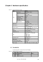
Table 3-12 JP1 Setting for the power supply source
JP1
USB Power
USB (1-2-pin short)
Battery
CN2 (2-3-pin short)
Please replace the battery with a new one, if the voltage level goes down to 4.75V.
Below the voltage level of 4.75V, functions of the board are not guaranteed.
The battery voltage can be checked at the port as shown below.
Chapter 3
Hardware specification
26
User's Manual U19026EE3V0UM00


