background image

123

8. Appendix

 Attaching the Optional Cable Cover (NP12CV)

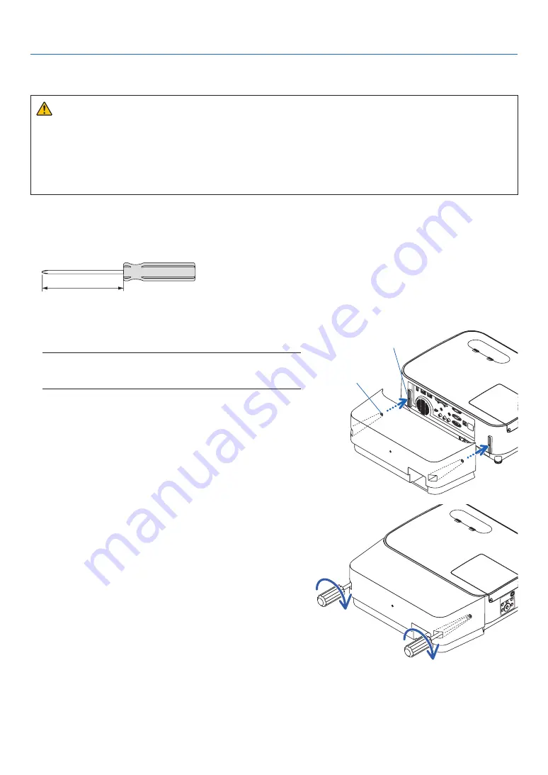
After finishing connections, attach the supplied cable cover to properly hide the cables.

 CAUTION:

•  Be sure to tighten the screws after attaching the cable cover. Failure to do so may cause the cable cover to 

come off and fall, resulting in injury or damage to the cable cover.

•  Do not put bundled cables in the cable cover. Doing so may damage the power cord, resulting in a fire.
•  Do not hold the cable cover while moving the projector or do not apply excessive force to the cable cover. 

Doing so may damage the cable cover, resulting in injury.

Attaching the cable cover

Tool needed:

•  Phillips screwdriver (plus-head) about 12 cm/4.7 inches in length

12 cm/4.7 inches

1.  Align the left and right fixing screw holes on the cable cover 

and the projector, and then put screws to each hole.

NOTE:

•  Be careful not to get cables caught in between the cable cover and the 

projector.

Cable cover fixing screw hole

Fixing screw

2.  Tighten the cable cover screws.

•  Be sure to tighten the screws.

Summary of Contents for P474U

Page 1: ...er s Manual Please visit our web site for User s Manual in the latest version http www nec display com dl en pj_manual lineup html The P604X and P603X are not distributed in North America Model No NP P554U NP P474U NP P554W NP P474W NP P604X NP P603X ...

Page 2: ...ed Access WPA WPA2 are registered trademarks of the Wi Fi Alliance Blu ray is a trademark of Blu ray Disc Association CRESTRON and ROOMVIEW are registered trademarks of Crestron Electronics Inc in the United States and other countries Extron and XTP are registered trademarks of RGB Systems Inc in the United States Ethernet is either a registered trademark or trademark of Fuji Xerox Co Ltd Android ...

Page 3: ...iod of time Doing so can result in these images being temporarily sustained on the surface of the LCD panel If this should happen continue to use your projector The static background from previous images will disappear Disposing of your used product In the European Union EU wide legislation as implemented in each Member State requires that used electrical and electronic products carrying the mark ...

Page 4: ...eorient or relocate the receiving antenna Increase the separation between the equipment and receiver Connect the equipment into an outlet on a circuit different from that to which the receiver is connected Consult the dealer or an experienced radio TV technician for help For UK only In UK a BS approved power cord with moulded plug has a Black five Amps fuse installed for use with this equipment If...

Page 5: ...nd immediately after the projector is turned off Parts of the projector may become temporarily heated if the projector is turned off with the POWER button or if the AC power supply is disconnected during normal projector operation Use caution when picking up the projector Prevent foreign objects such as paper clips and bits of paper from falling into your projector Do not attempt to retrieve any o...

Page 6: ...f the projector exhibits a distinct change in performance indicating a need for service Disconnect the power cord and any other cables before carrying the projector Turn off the projector and unplug the power cord before cleaning the cabinet or replacing the lamp Turn off the projector and unplug the power cord if the projector is not to be used for an extended period of time When using a LAN cabl...

Page 7: ...e that no one is under the projector Glass fragments could fall if the lamp has been burned out About High Altitude mode Set FAN MODE to HIGH ALTITUDE when using the projector at altitudes approximately 5500 feet 1700 meters or higher Using the projector at altitudes approximately 5500 feet 1700 meters or higher without setting to HIGH ALTITUDE can cause the projector to overheat and the protector...

Page 8: ...ODE the following terminals and functions will not work MONITOR OUT terminal AUDIO OUT terminal LAN functions Mail Alert function DDC CI Virtual Remote Tool Please refer to page 74 about details When NETWORK STANDBY has been set for STANDBY MODE and the LAN has been in link down condition for 3 minutes STANDBY MODE will transit into NORMAL automatically for the purpose to save the consumption powe...

Page 9: ...u Language Select screen 13 Selecting a Source 14 Selecting the computer or video source 14 Adjusting the Picture Size and Position 15 Adjusting the vertical position of a projected image Lens shift 16 Focus 18 Zoom 18 Adjust the Tilt Foot 19 Correcting Keystone Distortion KEYSTONE 20 Optimizing Computer Signal Automatically 22 Adjusting the Image Using Auto Adjust 22 Turning Up or Down Volume 22 ...

Page 10: ...ONS 60 AUDIO 64 Menu Descriptions Functions SETUP 65 GENERAL 65 MENU 67 INSTALLATION 69 OPTIONS 1 72 OPTIONS 2 74 Setting up the Projector for a Wired LAN Connection WIRED LAN 77 Setting up the Projector for a Wireless LAN Connection with the optional USB Wireless LAN Unit equipped WIRLESS LAN 78 Menu Descriptions Functions INFO 80 USAGE TIME 80 SOURCE 1 81 SOURCE 2 81 HDBaseT not supported by P60...

Page 11: ...108 8 Appendix 113 Troubleshooting 113 Feature of each indicator 113 Indicator Message Status message 113 Indicator Message Error message 115 Explanation on the POWER indicator and standby state 116 Common Problems Solutions 118 If there is no picture or the picture is not displayed correctly 119 Specifications 120 Cabinet Dimensions 122 Attaching the Optional Cable Cover NP12CV 123 5 Pin Assignme...

Page 12: ...ap strap 1 24J23901 Computer cable VGA 7N520089 Strap for MultiPresenter Stick 1 24J41711 NEC Projector CD ROM User s manual PDF 7N952602 For North America only Limited warranty For customers in Europe You will find our current valid Guarantee Policy on our Web Site www nec display solutions com Important Infomation 7N8N8492 Quick Setup Guide 7N8N8512 Remote control 7N901122 Batteries AAA 2 Unless...

Page 13: ...f and in the INFO of the on screen menu Lamp life up to 8000 hours Using in Eco Mode ECO allows you to prolong the projector s lamp life up to 8000 hours up to 4000 hours in ECO MODE OFF Wide range of input terminals HDMI 2 HDBaseT etc The projector is equipped with a variety of input terminals HDMI 2 Computer analog Video HDBaseT etc HDMI input terminal on this product supports HDCP HDBaseT is a ...

Page 14: ... higher or lower resolution than the projector s native resolution P554U P474U 1920 1200 P554W P474W 1280 800 P604X P603X 1024 768 will be displayed with Advanced AccuBlend 2 When WXGA MODE is set to ON CRESTRON ROOMVIEW and Extron XTP compatibility The projector supports CRESTRON ROOMVIEW and Extron XTP allowing multiple devices connected in the network to be managed and controlled from a compute...

Page 15: ... Ring page 18 Intake Vent Filter Cover page 105 111 Zoom Lever page 18 Lens Cap For protecting lens Make sure to take it off during projection Indicators page 6 Adjustable Tilt Foot page 19 Adjustable Tilt Foot Lever page 19 Exhaust Vent Heated air is exhausted from here Remote Sensor page 9 ...

Page 16: ...mote Sensor page 9 Rear Foot page 19 Controls page 6 Rear AC Input Connect the supplied power cord s three pin plug here and plug the other end into an active wall outlet page 11 Security chain opening Attach an anti theft device The security chain opening accepts security wires or chains up to 0 18 inch 4 6 mm in diameter This security slot supports the MicroSaver Security System ...

Page 17: ...2 23 2 POWER Indicator page 11 12 23 113 3 STATUS Indicator page 113 4 LAMP Indicator page 108 113 5 ECO Button page 26 6 SOURCE Button page 14 7 AUTO ADJ Button page 22 8 MENU Button page 51 9 Volume Buttons Keystone Buttons page 20 22 28 51 10 ENTER Button page 51 11 EXIT Button page 51 ...

Page 18: ...UT Terminal Mini D Sub 15 Pin page 95 7 AUDIO OUT Mini Jack Stereo Mini page 95 8 VIDEO IN Terminal RCA page 96 9 AUDIO IN L R RCA page 96 10 LAN Port RJ 45 page 99 11 USB Port Type A For USB memory page 100 12 PC CONTROL Port D Sub 9 Pin page 127 Use this port to connect a PC or control system This enables you to control the projector using serial communication protocol If you are writing your ow...

Page 19: ...4 103 13 USB B Button This button does not work on this series of projectors 14 APPS Button page 14 45 15 ID SET Button page 71 16 Numeric Keypad Button CLEAR Button page 71 17 FREEZE Button page 25 18 AV MUTE Button page 25 19 MENU Button page 51 20 EXIT Button page 51 21 Button page 51 22 ENTER Button page 51 23 D ZOOM Button page 25 26 24 MOUSE L CLICK Button This button does not work on this s...

Page 20: ...e control for a long time remove the batteries Ensure that you have the batteries polarity aligned correctly Do not use new and old batteries together or use different types of batteries together Dispose of used batteries according to your local regulations Operating Range for Wireless Remote Control 30 30 30 30 30 30 30 30 22 feet 7 m 22 feet 7 m Remote sensor on projector cabinet Remote control ...

Page 21: ...tor page 12 Step 3 Selecting a source page 14 Step 4 Adjusting the picture size and position page 15 Correcting keystone distortion KEYSTONE page 20 Step 5 Adjusting a picture and sound Optimizing a computer signal automatically page 22 Turning up or down volume page 22 Step 6 Making a presentation Step 7 Turning off the projector page 23 Step 8 When Moving the Projector page 24 2 Projecting an Im...

Page 22: ...cord to the projector First connect the supplied power cord s three pin plug to the AC IN of the projector and then connect the other plug of the supplied power cord in the wall outlet The projector s power indicator will start blinking orange This will apply for both indicators when NORMAL is selected for STANDBY MODE See the Power Indicator section page 113 COMPUTER IN Make sure that the prongs ...

Page 23: ...icator will blink and the projector will become ready to use TIP When the message Projector is locked Enter your password is displayed it means that the SECURITY feature is turned on page 33 After you turn on your projector ensure that the computer or video source is turned on NOTE When no input signal is present the no signal guidance is displayed factory menu setting Standby Blinking Power On Bl...

Page 24: ...e projector is too high the projector detects abnormal high temperature In this condition the projector will not turn on to protect the internal system If this happens wait for the projector s internal components to cool down When the lamp reaches its end of usable life the projector will not turn on If this happens replace the lamp If the STATUS indicator lights orange with the power button press...

Page 25: ... time the projector is turned on 1 Press the MENU button The menu will be displayed 2 Press the button twice to select SETUP and the button or the ENTER button to select GENERAL 3 Press the button four times to select OPTIONS 2 4 Press the button five times to select DEFAULT SOURCE SE LECT and press the ENTER button The DEFAULT SOURCE SELECT screen will be displayed page 75 5 Select a source as th...

Page 26: ...is chapter drawings and cables are omitted for clarity Adjusting the projected image s vertical and horizontal position Lens shift page 16 Adjusting the focus Focus ring page 18 Finely adjusting the size of an image Zoom lever page 18 Adjusting the throw angle the height of an image Tilt foot page 19 Adjusting the left and right tilt of an image Rear foot page 19 Correcting the keystone distortion...

Page 27: ...ust the projection position in the horizontal direction Lens shift dial Horizontal Lens shift dial Vertical Upward Leftward Downward Rightward NOTE The dials can be turned more than one full turn but the projection position cannot be moved more than the range indicated on the following page Do not force to turn the dials Doing so may damage the dials If the lens is shifted to the maximum in the di...

Page 28: ...e CEILING FRONT projection see page 91 P554U P474U P554W P474W 100 V 55 V 100 H 15 H 15 H 15 H 15 H Height of projected image Width of projected image P604X P603X 100 V 50 V 100 H 15 H 15 H 15 H 15 H Height of projected image Width of projected image Description of symbols V indicates vertical height of the projected image H indicates horizontal width of the projected image ...

Page 29: ... best focus NOTE Recommend to perform the focus adjustment after leaving the projector under the state the TEST PATTERN has been projected for over 30 minutes Please refer page 72 about the TEST PATTERN Focus ring Zoom Turn the zoom lever clockwise and counterclockwise Zoom lever ...

Page 30: ...imately 10 degrees up of adjustment for the front of the projector Rotate the rear foot to the desired height in order to square the image on the projection surface CAUTION Do not use the tilt foot for purposes other than originally intended Misuses such as using the tilt foot to carry or hang from the wall or ceiling the projector can cause damage to the projector Adjusting the left and right til...

Page 31: ...lue of either CONERSTONE or PINCUSHION has corrected KEYSTONE HORIZONTAL and KEYSTONE VERTICAL are disabled In this case RESET the corrected values and restart to correct distortion 1 Press the button on the projector cabinet The Keystone screen will be displayed on the screen Press the KEYSTONE button when using the remote control See page for PINCUSHION See page for CORNERSTONE See page for RESE...

Page 32: ...n The Keystone screen will disappear To perform Keystone correction again press the button to display the Keystone screen and repeat above steps 1 to 6 To return the keystone adjustments to default 1 Press the button to select RESET and press the ENTER button 2 Press the or button to select YES and press the ENTER button The adjustments will be reset All the adjustments for all the five items will...

Page 33: ...eration cannot optimize the computer signal try to adjust HORIZONTAL VERTICAL CLOCK and PHASE manually page 60 61 Turning Up or Down Volume Sound level from the speaker or audio output can be adjusted TIP When no menus appear the and buttons on the projector cabinet work as a volume control NOTE Volume control is not available with the or button when an image is magnified by using the D ZOOM butto...

Page 34: ... selected for STANDBY MODE Power On Steady blue light Standby Blinking orange light CAUTION Parts of the projector may become temporarily heated if the projector is turned off with the POWER button or if the AC power supply is disconnected during normal projector operation Use caution when picking up the projector NOTE While the power indicator is blinking blue in short cycles the power cannot be ...

Page 35: ...Moving the Projector Preparation Make sure that the projector is turned off 1 Put on the lens cap 2 Unplug the power cord 3 Disconnect any other cables Remove the USB memory or the wireless LAN Unit if it is inserted into the projector page 47 102 ...

Page 36: ...original level temporarily To restore the image even if you press the AV MUTE button immediately after the start of the power saving function the lamp brightness may not be restored to its original level Freezing a Picture Press the FREEZE button to freeze a picture Press again to resume motion NOTE The image is frozen but the original video is still playing back This feature can not be used when ...

Page 37: ...tween OFF and NORMAL automatically according to picture level NOTE A bright gradation may be less visible depending on the image NORMAL Lamp power consumption approx 80 bright ness on P554U P554W P604X P603X and approx 86 on P474U P474W The lamp life will extend by lowering the lamp power ECO Lamp power consumption approx 60 brightness on P554U P554W P604X P603X and approx 65 on P474U P474W The la...

Page 38: ...e will show energy saving effect in terms of CO2 emission reduction kg when the projector s ECO MODE is set to AUTO ECO NORMAL or ECO This feature is called as CARBON METER There are two messages TOTAL CARBON SAVINGS and CARBON SAVINGS SESSION The TOTAL CARBON SAVINGS message shows the total amount of CO2 emission reduction from the time of shipment up to now You can check the information on USAGE...

Page 39: ...d KEYSTONE VERTICAL are disabled In this case RESET the corrected values and restart to correct distortion Cornerstone 1 Press the KEYSTONE button with no menu displayed P554W P474W P604X P603X P554U P474U The KEYSTONE screen will be displayed Press the KEYSTONE button when using the remote control See page for PINCUSHION 2 Press the button to select CORNERSTONE and press the ENTER button The draw...

Page 40: ...move the projected image frame as shown on the example 8 Press the ENTER button 9 Use the button to select another icon which points in the direction On the Cornerstone adjustment screen select EXIT or press the EXIT button on the remote control The confirmation screen is displayed 10 Press the or button to highlight the OK and press the ENTER button This completes the Cornerstone correction Selec...

Page 41: ...e or button to select PINCUSHION LEFT RIGHT or PINCUSHION TOP BOTTOM 3 Press the or button to correct distortion NOTE The PINCUSHION LEFT RIGHT or PINCUSHION TOP BOTTOM item is not available when KEYSTONE HORIZONTAL KEYSTONE VERTICAL or COR NERSTONE is activated Before performing correction set the lens shift to the center position 4 Press the EXIT when PINCUSHION adjustment is completed P554U P47...

Page 42: ...hen KEYSTONE HORIZONTAL KEYSTONE VERTICAL or CORNERSTONE is activated Before performing correction set the lens shift to the center position 5 Press the EXIT when PINCUSHION adjustment is completed NOTE Even when the projector is turned on the last used correction values are applied PINCUSHION and CORNERSTONE corrections can cause the image to be slightly blurred because the correction is made ele...

Page 43: ...press ENTER button Confirmation message is displayed on 2 Move the cursor onto YES using either or button and then press the ENTER NOTE All adjusted values set in the KEYSTONE adjustment are reset to initial values TIP Adjustable range of the KEYSTONE and the CORNERSTONE Horizontal Direction Vertical Direction CORNERSTONE Approx 20 Max Approx 30 Max KEYSTONE Adjustable range may be narrower depend...

Page 44: ... menu To enable the Security function 1 Press the MENU button The menu will be displayed 2 Press the button twice to select SETUP and press the button or the ENTER button to select GEN ERAL 3 Press the button to select INSTALLATION 4 Press the button three times to select SECURITY and press the ENTER button The OFF ON menu will be displayed 5 Press the button to select ON and press the ENTER butto...

Page 45: ...n enabled To turn on the projector when SECURITY is enabled 1 Press the POWER button The projector will be turned on and display a message to the effect that the projector is locked 2 Press the MENU button 3 Type in the correct keyword and press the ENTER button The projector will display an image NOTE The security disable mode is maintained until the main power is turned off or unplugging the pow...

Page 46: ... button The SECURITY KEYWORD screen will be displayed 4 Type in your keyword and press the ENTER button When the correct keyword is entered the SECURITY function will be disabled NOTE If you forget your keyword contact your dealer Your dealer will provide you with your keyword in exchange for your request code Your request code is displayed in the Keyword Confirmation screen In this example NB52 Y...

Page 47: ...d down or operation may not be accepted depending the settings of your network Should this happen consult your network administrator The projector may not respond if its buttons are repeatedly pressed in rapid intervals Should this happen wait a moment and repeat If you still can t get any response turn off and back on the projector If the PROJECTOR NETWORK SETTINGS screen does not appear in the w...

Page 48: ...ting by specifying http pj nec co jp index html for the address or the entry column of the URL Example 2 When the IP address of the projector is 192 168 73 1 access is gained to the network setting by specifying http 192 168 73 1 index html for the address or the entry column of the URL PROJECTOR ADJUSTMENT POWER This controls the power of the projector ON Power is switched on OFF Power is switche...

Page 49: ...projector page 59 SOURCE SELECT This switches the input terminal of the projector HDMI1 Switches to the HDMI 1 IN terminal HDMI2 Switches to the HDMI 2 IN terminal COMPUTER Switches to the COMPUTER IN terminal VIDEO Switches to the VIDEO IN terminal HDBaseT Switch to image input sent from a transmission device that supports HDBaseT not supported by P603X USB A Switches to the data on the USB memor...

Page 50: ...he network connected to the projector GATEWAY Set the default GATEWAY of the network connected to the projector AUTO DNS ON DHCP server will automatically assign IP ADDRESS of DNS server connected to the projector AUTO DNS OFF Set your IP ADDRESS of DNS server connected to the projector APPLY Make the settings for wired LAN effective WIRELESS LAN SIMPLE ACCESS POINT Set the projector as a simple a...

Page 51: ... to the projector GATEWAY Set the default GATEWAY of the network connected to the projector AUTO DNS ON DHCP server will automatically assign IP ADDRESS of DNS server connected to the projector AUTO DNS OFF Set your IP ADDRESS of DNS server connected to the projector CONNEC TION SSID Enter an identifier SSID as an access point SSID must be 1 to 32 alphanumeric characters including a space SECURITY...

Page 52: ... NEC Projector Lamp Hours Used 100 H SENDER S ADDRESS Enter sender s address SMTP SERVER NAME Enter the SMTP server name to be connected to the projector RECIPIENT S ADDRESS 1 2 3 Enter your recipient s address Up to three addresses can be entered TEST MAIL Send a test mail to check whether your settings are correct or not NOTE If you execute a test you may not receive an Alert mail Should this ha...

Page 53: ...sed for controlling projectors of different manufacturers This standard protocol is established by Japan Business Machine and Information System Industries Association JBMIA in 2005 The projector supports all the commands of PJLink Class 1 Setting of PJLink will not be affected even when RESET is done from the menu CRESTRON ROOMVIEW compatibility The projector supports CRESTRON ROOMVIEW allowing m...

Page 54: ...able presentations can be conducted simply with the projector Supported graphic format is JPEG The Viewer displays the thumbnail screen JPEG Exif only on which you can jump to any specific image you wish to project There are two ways of playback for slideshow manual playback and auto playback The interval time can be changed in auto playback The order of displaying images can be set by name date o...

Page 55: ...our USB memory check if the format is supported To format your USB memory in your computer refer to the document or help file that comes with your Windows We do not warrant that the USB port of the projector will support all USB memories in the market Supported images Supported file format for Viewer are as follows We do not warrant all the images are supported for Viewer Images other than mention...

Page 56: ...rom the projector page 47 Exiting the Viewer page 47 Preparation Before starting the Viewer store images to the USB memory using your computer Starting the Viewer 1 Turn on the projector page 12 2 Insert the USB memory into the USB port of the projec tor Do not remove the USB memory from the projector while it s LED flashes Doing so may corrupt the data 3 Press the SOURCE button on the projector c...

Page 57: ...ton to select the next slide The slide on the right will be displayed The or button can be used to select the next right slide or the previous left slide in the thumbnail screen Pressing the MENU button during display of the thumbnail screen the slide screen or the slideshow screen will display the toolbar The toolbar is used to select or rotate an slide page 50 8 Press the EXIT button when the to...

Page 58: ...rojector may not operate correctly If this happens turn off the projector and unplug the power cord Wait 3 minutes then connect the power cord and turn on the projector Exiting the Viewer 1 Press the MENU button with the slide screen or the thumbnail screen displayed The control bar or the pop up menu will be displayed 2 Press the MENU button again The on screen menu will be displayed 3 Select a s...

Page 59: ... button 5 Back icon This icon is used to return to the upper parent folder 6 Folder icon This icon shows that the USB memory has folders 7 Page up Page down icon This icon shows further folders or image files are available in the next previous page Use the button to go to the next previous row The PAGE or PAGE on the remote control is used to go to the next or previous page directly 8 Thumbnail to...

Page 60: ...be displayed Press the MENU button again to close the SOURCE list Thumbnail toolbar Menu Options Description 1 Back Goes back to the previous image When the cursor reaches the top left of the screen it will go to the previous page 2 Forward Goes to the next image When the cursor reaches the bottom right of the screen it will go to the next page 3 Display Closes the menu and returns to the thumbnai...

Page 61: ...ise 4 Counter clockwise rotation Close the menu and rotate the image 90 counter clockwise Slideshow toolbar Menu Options Description 1 Stop Closes the menu and changes to the slide screen 2 Back Goes back to the previous image 3 Forward Goes to the next image 4 Interval Specifies interval time when playing back the slides 5 Repeat Repeats to play back the images in the folder Returns to the thumbn...

Page 62: ...projector cabinet to select the item you want to adjust or set You can use the buttons on the remote control or the projector cabinet to select the tab you want 5 Press the ENTER button on the remote control or the projector cabinet to display the submenu window 6 Adjust the level or turn the selected item on or off by using the buttons on the remote control or the projector cabinet Changes are st...

Page 63: ...n to select an option in a dialog box Source Indicates the currently selected source Off Timer remaining time Indicates the remaining countdown time when the OFF TIMER is preset Slide bar Indicates settings or the direction of adjustment ECO mode symbol Indicates ECO MODE is set Key Lock symbol Indicates the CONTROL PANEL LOCK is enabled Thermometer symbol Indicates the ECO MODE is forcibly set to...

Page 64: ...RBOX NATIVE P604X P603X AUTO 4 3 16 9 15 9 16 10 WIDE ZOOM NATIVE POSITION Not available on P554U P474U P554W P474W 0 AUDIO VOLUME 11 0 31 SETUP GENERAL KEYSTONE KEYSTONE HORIZONTAL 0 KEYSTONE VERTICAL 0 PINCUSHION LEFT RIGHT not available on P554U P474U 0 PINCUSHION TOP BOTTOM not available on P554U P474U 0 CORNERSTONE 0 PINCUSHION not available on P554W P474W P604X P603X TOP 0 BOTTOM 0 LEFT 0 RI...

Page 65: ...ENT RGB COMPONENT VIDEO AUTO AUTO NTSC3 58 NTSC4 43 PAL PAL M PAL N PAL60 SECAM WXGA MODE P554U P474U P554W P474W ON P604X P603X OFF OFF ON DEINTERLACE ON OFF ON HDMI SETTINGS HDMI1 VIDEO LEVEL AUTO AUTO NORMAL ENHANCED HDMI2 VIDEO LEVEL AUTO AUTO NORMAL ENHANCED HDBaseT not supported by P603X VIDEO LEVEL AUTO AUTO NORMAL ENHANCED AUDIO SELECT HDMI1 HDMI1 HDMI1 COMPUTER HDMI2 HDMI2 HDMI2 COMPUTER ...

Page 66: ...E BIT DEPTH 8 bits 10 bits 12 bits VIDEO LEVEL HDBaseT not supported by P603X SIGNAL QUALITY OPERATION MODE LINK STATUS HDMI STATUS WIRED LAN IP ADDRESS SUBNET MASK GATEWAY MAC ADDRESS WIRELESS LAN IP ADDRESS SUBNET MASK GATEWAY MAC ADDRESS SSID NETWORK TYPE SECURITY CHANNEL SIGNAL LEVEL VERSION FIRMWARE DATA OTHERS PROJECTOR NAME HOST NAME MODEL NO SERIAL NUMBER LAN UNIT TYPE CONTROL ID when CONT...

Page 67: ...o your COMPUTER input terminal signal NOTE When the component input signal is connected to the COMPUTER IN terminal select COMPUTER VIDEO Selects what is connected to your VIDEO input VCR DVD player or document camera HDBaseT not supported by P603X Projecting the HDBaseT signal USB A This feature enables you to make presentations using a USB memory that contains slides page 43 4 Using the Viewer ...

Page 68: ...brightly lit room PRESENTATION Recommended for making a presentation using a PowerPoint file VIDEO Recommended for typical TV program viewing MOVIE Recommended for movies GRAPHIC Recommended for graphics sRGB Standard color values DICOM SIM Recommended for DICOM simulation format NOTE The DICOM SIM option is for training reference only and should not be used for actual diagnosis DICOM stands for D...

Page 69: ...not available when DICOM SIM is selected for DETAIL SETTINGS Selecting Screen Size for DICOM SIM SCREEN SIZE This function will perform gamma correction appropriate for the screen size LARGE For screen size of 110 MEDIUM For screen size of 90 SMALL For screen size of 70 NOTE This function is available only when DICOM SIM is selected for DETAIL SETTINGS Adjusting Color Temperature COLOR TEMPERATURE...

Page 70: ...ess level or the back raster intensity SHARPNESS Controls the detail of the image COLOR Increases or decreases the color saturation level HUE Varies the color level from green to blue The red level is used as reference Input signal CONTRAST BRIGHTNESS SHARPNESS COLOR HUE COMPUTER HDMI HDBaseT RGB Yes Yes Yes No No COMPUTER HDMI HDBaseT COMPONENT Yes Yes Yes Yes Yes VIDEO Yes Yes Yes Yes Yes USB A ...

Page 71: ...nding that might appear This function adjusts the clock frequencies that eliminate the horizontal banding in the image This adjustment may be necessary when you connect your computer for the first time PHASE Use this item to adjust the clock phase or to reduce video noise dot interference or cross talk This is evident when part of your image appears to be shimmering Use PHASE only after the CLOCK ...

Page 72: ... signal The next time you project the signal with the same resolution horizontal and vertical frequency its adjustments will be called up and applied To delete adjustments stored in memory from the menu you select RESET CURRENT SIGNAL or ALL DATA and reset the adjustments Selecting Overscan Percentage OVERSCAN Select overscan percentage AUTO 0 5 and 10 for signal Projected image Overscaned by 10 N...

Page 73: ... displayed in 16 9 aspect ratio 15 9 The image is displayed in 15 9 aspect ratio 16 10 The image is displayed in 16 10 aspect ratio WIDE ZOOM P604X P603X The image is stretched left and right Parts of the displayed image are cropped at the left and right edges and therefore not visible LETTERBOX P554U P474U P554W P474W The image of a letterbox signal is stretched equally in the horizontal and vert...

Page 74: ...cally determined NOTE To display a letterbox signal properly select LETTERBOX NOTE To display a squeezed signal properly select 16 9 TIP Image position can be adjusted vertically using POSITION when the 16 9 15 9 or 16 10 aspect ratios are selected The term letterbox refers to a more landscape oriented image when compared to a 4 3 image which is the standard aspect ratio for a video source The let...

Page 75: ...ning Up or Down Sound Adjusts the volume of the projector speaker and AUDIO OUT Stereo Mini Jack TIP When no menus appear the and buttons on the projector cabinet and the VOL buttons on the remote control work as a volume control page 22 ...

Page 76: ...cally KEYSTONE HORIZONTAL Corrects horizontal keystone distortion page 20 KEYSTONE VERTICAL Corrects vertical keystone distortion page 20 PINCUSHION LEFT RIGHT Corrects pincushion distortion at the left or right side page 30 PINCUSHION TOP BOTTOM Corrects pincushion distortion at the top or bottom side page 30 CORNERSTONE Fits a projected image within the border of the screen easily by align the f...

Page 77: ...on in applications where the screen material is not white NOTE Selecting WHITEBOARD reduces lamp brightness Setting Eco Mode ECO MODE The ECO MODE increases lamp life while lowering power consumption and cutting down on CO2 emissions Four brightness modes of the lamp can be selected OFF AUTO ECO NORMAL and ECO modes page 26 ...

Page 78: ...The projector will turn off after the countdown is complete NOTE To cancel the preset time set OFF for the preset time or turn off the power When the remaining time reaches 3 minutes before the projector is turned off the THE PROJECTOR WILL TURN OFF WITHIN 3 MINUTES message will be displayed on the bottom of the screen Selecting Menu Language LANGUAGE You can choose one of 30 languages for on scre...

Page 79: ...touch of a button to turn off the menu The preset choices are MANUAL AUTO 5 SEC AUTO 15 SEC and AUTO 45 SEC The AUTO 45 SEC is the factory preset Selecting a Color or Logo for Background BACKGROUND Use this feature to display a blue black screen or logo when no signal is available The default background is BLUE NOTE If the LOGO item is selected for BACKGROUND with the HDBaseT source selected the B...

Page 80: ...ROL PANEL LOCK function NOTE This CONTROL PANEL LOCK does not affect the remote control functions When the control panel is locked pressing and holding the SOURCE button on the projector cabinet for about 10 seconds will change the setting to OFF TIP When the CONTROL PANEL LOCK is turned on a key lock icon will be displayed at the bottom right of the menu Enabling Security SECURITY This feature tu...

Page 81: ... to NORMAL or NETWORK STANDBY the power cannot be turned on The methods below can be used to turn on the projector s power when it is in the standby mode The projector can be operated by connecting the computer and projector by RS232C serial communications on the projector using the PC CONTROL terminal and the PC Control Utility application with STANDBY MODE set to NETWORK STANDBY The projector ca...

Page 82: ...ll display the menu for canceling the Control ID Assigning or Changing the Control ID 1 Turn on the projector 2 Press the ID SET button on the remote control The CONTROL ID screen will be displayed If the projector can be operated with the current remote control ID the ACTIVE will be displayed If the projector cannot be operated with the current remote control ID the INACTIVE will be displayed To ...

Page 83: ...des for fan speed Auto mode High speed mode and High Altitude mode AUTO The built in fans automatically run at a variable speed according to the internal temperature HIGH The built in fans run at high speed HIGH ALTITUDE The built in fans run at a high speed Select this option when using the projector at altitudes approximately 5500 feet 1700 meters or higher When you wish to cool down the tempera...

Page 84: ...time of shipment of P604X P603X ON is selected at the time of shipment of P554U P474U P554W P474W Enabling the deinterlace DEINTERLACE Turns on or off the deinterlace function for a telecine signal OFF Select this option if there is any jitter or artifacts in video ON Default standard setting NOTE This feature is not available for HDTV progressive and computer signals Setting HDMI1 HDMI2 and HDBas...

Page 85: ...TANDBY When NETWORK STANDBY is selected the projector can be turned on over a wired LAN connection and only the following buttons port and features will work POWER buttons on the projector cabinet and the remote control powering on from PC Control command AUTO POWER ON wireless LAN unit optional operation by User Supportware LAN feature and Mail Alert feature IMPORTANT When NETWORK STANDBY has bee...

Page 86: ...If a computer or HDMI signal is still present when the projector is turned off the AUTO POWER ON will not work and the projector remains in standby mode Depending on the projector in use theAUTO POWER ON may not work properly In this case set STANDBY MODE to NETWORK STANDBY Enabling Power Management AUTO POWER OFF When this option is selected you can enable the projector to automatically turn off ...

Page 87: ...CURRENCY CONVERT Changes currency setting and currency convert setting for CARBON METER The initial setting are as follows US Dollar 0 11 kWh EU Euro 0 19 kWh Japanese Yen 20 kWh Chinese Yuan 0 48 kWh The initial settings for US dollar EU Euro and Japanese Yen are based on Energy Prices and Taxes second quarter 2010 published by OECD The initial setting for Chinese Yuan is based on Chinese Data Fi...

Page 88: ... turned on SETTINGS DHCP ON IP address subnet mask and gateway will be automatically assigned to the projector from your DHCP server OFF Specify IP address subnet mask and gateway assigned by your network administrator IP ADDRESS Set your IP address of the network connected to the projector SUBNET MASK Set your subnet mask number of the network connected to the projector GATEWAY Set the default ga...

Page 89: ...FRASTRUCTURE Connect the projector to an access point RECONNECT Retry to connect the projector to a network Try this if you have changed PROFILE When you connect with your computer to save your profile and select Automatically connect when within range from the Properties tab of Wireless Network in Windows for your selected profile your wireless LAN will be accessed under the following conditions ...

Page 90: ...ues and then click APPLY to reflect these values to wireless LAN connection To select an SSID Access the HTTP server to display the web browser page 36 and select NETWORK SETTINGS SET TINGS WIRELESS LAN INFRASTRUCTURE and then click APPLY After completion of these steps click SETTING for the INFRASTRUCTURE and then click SITE SURVEY on the CONNECTION page finally select the SSID you want to connec...

Page 91: ...s 0 the LAMP LIFE REMAINING bar indicator changes from 0 to 100 Hours and starts counting down If the remaining lamp time reaches 0 hours the projector will not turn on The message to the effect that the lamp or the filters should be replaced will be displayed for one minute when the projector is turned on and when the POWER button on the projector or the remote control is pressed To dismiss this ...

Page 92: ...SOURCE NAME SOURCE INDEX HORIZONTAL FREQUENCY VERTICAL FREQUENCY SYNC TYPE SYNC POLARITY SCAN TYPE SOURCE 2 SIGNAL TYPE VIDEO TYPE BIT DEPTH VIDEO LEVEL HDBaseT not supported by P603X SIGNAL QUALITY OPERATION MODE LINK STATUS HDMI STATUS ...

Page 93: ...g On Screen Menu WIRED LAN IP ADDRESS SUBNET MASK GATEWAY MAC ADDRESS WIRELESS LAN IP ADDRESS SUBNET MASK GATEWAY MAC ADDRESS SSID NETWORK TYPE SECURITY CHANNEL SIGNAL LEVEL VERSION FIRMWARE Version DATA Version ...

Page 94: ...83 5 Using On Screen Menu OTHERS PROJECTOR NAME HOST NAME MODEL NO SERIAL NUMBER LAN UNIT TYPE CONTROL ID when CONTROL ID is set ...

Page 95: ...ESS LAN To reset the lamp usage time see Clearing Lamp Hour Meter CLEAR LAMP HOURS below Clearing Lamp Hour Meter CLEAR LAMP HOURS Resets the lamp clock back to zero Selecting this option displays submenu for a confirmation Select YES and press the ENTER button NOTE Elapsed time of the lamp use will not be affected even when RESET is done from the menu NOTE The projector will turn off and go into ...

Page 96: ...d to telescopic Screen center line telescopic Screen center line wide When zoom lever turned to wide Projector lens center m m When zoom lever turned to wide When zoom lever turned to telescopic The figures indicated for height of screen from projector lens center on the projection distance table are for a lens shift of 55 V Reading the Table From the upper table on this page to project wide image...

Page 97: ...enter m m When zoom lever turned to wide When zoom lever turned to telescopic The figures indicated for height of screen from projector lens center on the projection distance table are for a lens shift of 55 V Reading the Table From the upper table on this page to project wide images on a 100 screen install at about 2 7 m from the front Also from the lower table we can see that about 1 3 m are req...

Page 98: ...enter m m When zoom lever turned to wide When zoom lever turned to telescopic The figures indicated for height of screen from projector lens center on the projection distance table are for a lens shift of 50 V Reading the Table From the upper table on this page to project wide images on a 100 screen install at about 2 7 m from the front Also from the lower table we can see that about 1 5 m are req...

Page 99: ...134 6 120 101 8 258 5 63 6 161 5 150 123 3 313 1 79 5 201 9 200 169 6 430 8 106 0 269 2 240 203 5 516 9 127 2 323 1 300 254 4 646 2 159 0 403 9 P604X P603X Screen height Screen width Screen size diagonal Size inches Screen width Screen height inches cm inches cm 30 24 0 61 0 18 0 45 7 40 32 0 81 3 24 0 61 0 60 48 0 121 9 36 0 91 4 80 64 0 162 6 48 0 121 9 100 80 0 203 2 60 0 152 4 120 96 0 243 8 7...

Page 100: ...4 3 15 202 5 12 31 8 3 5 80 8 9 0 150 156 3 95 253 6 42 39 8 4 4 101 0 11 2 180 187 4 75 303 7 71 47 7 5 3 121 2 13 5 200 208 5 29 337 8 57 53 0 5 9 134 6 15 0 240 250 6 35 405 10 29 63 6 7 0 161 5 17 9 300 313 7 95 507 12 88 79 5 8 8 201 9 22 4 P554W P474W Screen surface Lower edge of screen with 55 V Measurement H Measurement H Lower edge of screen with 0 V Lens center Approximately 68 to 73 mm ...

Page 101: ... in Screen size inches Throw distance L Height H Wide Tele 0 V 50 V inches m inches m inches cm 30 30 0 75 51 1 31 9 0 0 22 9 0 40 41 1 03 70 1 77 12 0 0 30 5 0 60 63 1 59 106 2 69 18 0 0 45 7 0 80 84 2 15 142 3 61 24 0 0 61 0 0 100 106 2 70 179 4 54 30 0 0 76 2 0 120 128 3 26 215 5 46 36 0 0 91 4 0 150 161 4 09 269 6 84 45 0 0 114 3 0 180 194 4 93 324 8 23 54 0 0 137 2 0 200 216 5 48 360 9 15 60 ...

Page 102: ...e screen height and H Horizontal refers to the screen width The lens shift range is expressed as a ratio of height and width respectively P554U P474U P554W P474W Lens shifting range Vertical direction 55 0 Horizontal direction 15 100 V 55 V 100 H 15 H 15 H 15 H 15 H Height of projected image Width of projected image 100 V 55 V 100 H 15 H 15 H 15 H 15 H Height of projected image Width of projected ...

Page 103: ...y 18 45 7 cm Figures differ by several because the calculation is approximate WARNING Installing your projector on the ceiling must be done by a qualified technician Contact your NEC dealer for more information Do not attempt to install the projector yourself Only use your projector on a solid level surface If the projector falls to the ground you can be injured and the projector severely damaged ...

Page 104: ...urning on the projector Input terminal SOURCE button on the projector cabinet Button on the remote control COMPUTER IN COMPUTER COMPUTER 1 HDMI 1 IN HDMI1 HDMI 1 HDMI 2 IN HDMI2 HDMI 2 HDMI 1 IN HDMI 2 IN COMPUTER IN AUDIO IN Computer cable VGA supplied To mini D Sub 15 pin terminal on the projector It is recommended that you use a commercially available distribution amplifier if connecting a sign...

Page 105: ... a DVI signal When the computer has a DVI output terminal use a commercially available converter cable to connect the com puter to the projector s HDMI 1 or HDMI 2 input terminal only digital video signals can be input HDMI 1 IN HDMI 2 IN AUDIO IN NOTE When Viewing a DVI Digital Signal Turn off the power of the computer and projector before connecting When a video deck is connected via a scan conv...

Page 106: ...pped In this case pull out the computer cable and set it back after inputting video signal Monitor out and sleep mode The COMPUTER OUT terminal will not work when NORMAL is selected for STANDBY MODE The COMPUTER OUT terminal will work only in the sleep mode Applying a signal from the COMPUTER IN terminal will put the projector in the sleep mode which allows you to use the COMPUTER OUT terminal and...

Page 107: ...he source name for its appropriate input terminal after turning on the projector Input terminal SOURCE button on the projector cabinet Button on the remote control VIDEO IN VIDEO VIDEO NOTE Refer to your VCR owner s manual for more information about your equipment s video output requirements NOTE An image may not be displayed correctly when a Video source is played back in fast forward or fast rew...

Page 108: ...ignal will be automatically displayed If not from the menu select SETUP OPTIONS 1 SIGNAL SELECT COMPUTER and then place a check mark in the Component radio button Select the source name for its appropriate input terminal after turning on the projector Input terminal SOURCE button on the projector cabinet Button on the remote control COMPUTER IN COMPUTER COMPUTER 1 NOTE Refer to your DVD player s o...

Page 109: ...or cabinet Button on the remote control HDMI 1 IN HDMI1 HDMI1 HDMI 2 IN HDMI2 HDMI2 When connecting the HDMI1 IN terminal or HDMI2 terminal of the projector to the DVD player the projector s video level can be made settings in accordance with the DVD player s video level In the menu select HDMI SETTINGS VIDEO LEVEL and make necessary settings If the HDMI input sound cannot be heard in the menu sel...

Page 110: ...ard with a LAN port RJ 45 which provides a LAN connection using a LAN cable To use a LAN connection you are required to set the LAN on the projector menu Select SETUP WIRED LAN page 77 Example of LAN connection Server Hub LAN cable not supplied NOTE Use a Category 5 or higher LAN cable ...

Page 111: ...cessive force applied the USB port may break Before touching the USB Wireless LAN Unit touch a metallic object such as a door knob or aluminum window frame to discharge the static electricity from your body Always insert or remove the USB Wireless LAN unit when the main power is turned off Failure to do so may cause projector malfunction or damage to the USB wireless LAN unit If the projector will...

Page 112: ...r frame around the buttons until a click sound is heard The filter cover will be secured in position To remove the USB Wireless LAN Unit disconnect the power cord and use the above procedure NOTE Do not press the button on the USB Wireless LAN Unit The button does not work with this model ...

Page 113: ...TP server to set the wireless LAN page 39 Select either SIMPLE ACCESS POINT or INFRASTRUCTURE for WIRELESS in SETTINGS of NETWORK SETTINGS and then perform detail settings in SETTING 4 Click APPLY to connect to the wireless LAN NOTE To use the HTTP server function the projector must be connected to a network First connect the projector to a network by the wired LAN and then perform required settin...

Page 114: ...l device are only supported when the projector s power is turned on Connection example HDBaseT Computer for control use Computer for output use Example of a transmission device Remote control HDMI output video device NOTE Please use a shielded twisted pair STP cable of Category 5e or higher for the LAN cable sold commercially The maximum transmission distance over the LAN cable is 100 m Please do ...

Page 115: ...1 The projector can be operated by connecting the computer and projector to the network on the projector using the LAN port with STANDBY MODE set to NETWORK STANDBY HDBaseT DC IN HDBaseT Computer for projector control Computer for output Example of a transmitter Switching hub etc Video device with HDMI output 2 The projector can be operated by RS232C serial communication On this projector use the ...

Page 116: ...me of shipment To cancel the message press any button on the projector cabinet or the remote control To clean the filter detach the filter unit and the filter cover CAUTION Before cleaning the filters turn off the projector disconnect the power cord and then allow the cabinet to cool Failure to do so can result in electric shock or burn injuries 1 Press down two buttons and then pull the filter co...

Page 117: ... the buttons until a click sound is heard The filter cover will be secured in position 6 Clear the filter usage hours Plug the power cord into the wall outlet and then turn on the projector From the menu select RESET CLEAR FILTER HOURS page 84 The interval time to clean the filters is set to OFF at time of shipment When using the projector as it is you do not clear the filter usage ...

Page 118: ...e dust off the cabinet If heavily soiled use a mild detergent Never use strong detergents or solvents such as alcohol or thinner When cleaning the vents or the speaker using a vacuum cleaner do not force the brush of the vacuum cleaner into the slits of the cabinet Vacuum the dust off the vents Clogged vents may cause a rise in the internal temperature of the projector resulting in malfunction Do ...

Page 119: ...surface on the lamp housing Leaving finger prints on the glass surface might cause an unwanted shadow and poor picture quality The projector will turn off and go into standby mode when you continue to use the projector for another 100 hours after the lamp has reached the end of its life If this happens be sure to replace the lamp If you continue to use the lamp after the lamp reaches the end of it...

Page 120: ...le There is an interlock on this case to prevent the risk of electrical shock Do not attempt to circumvent this interlock 2 Remove the lamp housing by holding it CAUTION Make sure that the lamp housing is cool enough before removing it To replace the lamp 1 Remove the lamp cover 1 Loosen the lamp cover screw The lamp cover screw is not removable 2 Push and slide the lamp cover off Interlock ...

Page 121: ...ntrol for 10 seconds to reset the lamp clock back to zero When the lamp time clock is reset to zero the LAMP indicator goes out 4 Reattach the lamp cover 1 Slide the lamp cover back until it snaps into place 2 Tighten the screw to secure the lamp cover Be sure to tighten the screw 3 Install a new lamp housing 1 Insert a new lamp housing until the lamp housing is plugged into the socket 2 Push the ...

Page 122: ... place Incorrect attachment of a filter may cause dust and dirt to get into the inside of the projector 1 Press down on the buttons on the left and right and then pull the filter cover towards you to open it The cover will open about 90 degrees before it stops Filter cover 2 Pick the center of the filter unit for pulling it out Filter unit 3 Remove dust from the filter cover Clean both outside and...

Page 123: ... to the clearing lamp and filter hour meters To clear the lamp usage hours and the filter usage hours 1 Place the projector where you use it 2 Plug the power cord into the wall outlet and then turn on the projector 3 Clear the lamp usage hours and the filter usage hours 1 From the menu select RESET CLEAR LAMP HOURS and reset the lamp usage hours 2 Select CLEAR FILTER HOURS and reset the filter usa...

Page 124: ...forms the state of lamp usage time of the lamp and the status of ECO MODE Indicator Message Status message POWER STATUS LAMP Projector status Power is off Off Off Off In the state of Standby Standby mode is NETWORK STANDBY and network is ready Orange Blink 1 Off Off In the state of Standby Network is unavailable Orange Blink 2 Off Off In the state of Standby Standby mode is NETWORK STANDBY and net...

Page 125: ... timer is activated Powered state Blue Blink 3 Off Status varies Preparing for powering ON Blue Blink 4 Off Off 1 Repetition to light on for 1 5 seconds off for 1 5 seconds 2 Repetition to light on for 1 5 seconds off for 7 5 seconds 3 Repetition to light on for 2 5 seconds off for 0 5 seconds 4 Repetition to light on for 0 5 seconds off for 0 5 seconds ...

Page 126: ...Blink 4 Off Off Lamp does not light Wait at least 1 minute then turn on the power back on if the lamp still does not light contact your dealer or service personnel Red Blink 4 Green Light Red Light Lamp cover problem Lamp cover is not mounted properly Mount it see page 110 Red Blink 4 Red Light Green Light Error requiring service support Contact your dealer or service personnel Make sure to check ...

Page 127: ...twork is linked Link up network Link down network No operation Link down network No signal input for approx 180 seconds Link down for approx 180 seconds No operation No communication with the link up network No signal input for approx 180 seconds Power Off Power On Power On Input signal Indicator Blinks in orange with long interval Standby state The network is unavailable Power On Input signal Ind...

Page 128: ...available HDBaseT LAN PC CON TROL Power consumption High Low Indicator Lights in blue Powered ON state Power On No operation No signal input for approx 10 seconds Power Off Power On Indicator Blinks in orange with long interval Standby state The network is unavailable Indicator Lights in green Sleep state ...

Page 129: ...ot turned on unless connected to the projector before being powered up If the screen goes blank while using your remote control it may be the result of the computer s screen saver or power management software See also the next page Picture suddenly be comes dark Check if the projector is in the Forced ECO mode because of too high ambient temperature If this is the case lower the internal temperatu...

Page 130: ... the projected image may not be displayed correctly Should this happen deactivate the notebook PC s LCD screen when the projector display is in use Each notebook PC has a different way of deactivate reactivate the local LCD screens as described in the previ ous step Refer to your computer s documentation for detailed information Image displayed is incorrect when using a Mac When using a Mac with t...

Page 131: ...BRIGHT If any other mode is selected as the PRESET mode the light output value may drop slightly 3 Compliance with ISO21118 2012 4 The maximum power becomes equivalent to power in NORMAL ECO MODE Electrical Model Number P554U P474U P554W P474W P604X P603X Inputs 1 RGB Component D Sub 15 P 2 HDMI Type A 19P HDMI Terminal HDCP supported 5 1 Video RCA 1 HDBaseT 1 L R RCA Audio 1 Stereo Mini Audio 1 R...

Page 132: ... ECO 286 W 100 130 V 277 W 200 240 V 280 W 100 130 V 267 W 200 240 V 273 W 100 130 V 258 W 200 240 V STANDBY NETWORK STANDBY 2 0 W 100 130 V 2 1 W 200 240 V 2 0 W 100 130 V 2 0 W 200 240 V STANDBY NORMAL 0 14 W 100 130 V 0 17 W 200 240 V 0 16 W 100 130 V 0 2 W 200 240 V 6 An image with higher or lower resolution than the projector s native resolution P604X P603X 1024 768 P554W P474W 1280 800 P554U...

Page 133: ...122 8 Appendix 420 16 5 175 6 9 70 2 8 195 7 7 5 0 2 141 5 5 6 329 3 13 68 8 2 7 133 5 2 130 5 1 150 5 9 141 5 5 322 12 7 Cabinet Dimensions Unit mm inch Lens center ...

Page 134: ... resulting in a fire Do not hold the cable cover while moving the projector or do not apply excessive force to the cable cover Doing so may damage the cable cover resulting in injury Attaching the cable cover Tool needed Phillips screwdriver plus head about 12 cm 4 7 inches in length 12 cm 4 7 inches 1 Align the left and right fixing screw holes on the cable cover and the projector and then put sc...

Page 135: ...le cover 1 Loosen the cable cover screws until the Phillips screw driver goes into a freewheeling condition and remove the cover When suspended from the ceiling hold so that the cable cover does not drop The screws cannot be removed ...

Page 136: ... 6 9 7 8 Pin No RGB Signal Analog YCbCr Signal 1 Red Cr 2 Green or Sync on Green Y 3 Blue Cb 4 Ground 5 Ground 6 Red Ground Cr Ground 7 Green Ground Y Ground 8 Blue Ground Cb Ground 9 Hotplug 10 Sync Signal Ground 11 No Connection 12 Bi directional DATA SDA 13 Horizontal Sync or Composite Sync 14 Vertical Sync 15 Data Clock COMPUTER IN NOTE Pin Nos 12 and 15 are required for DDC CI ...

Page 137: ...ignals are not supported Signals other than those specified in the table above may not be displayed correctly If this should happen change the refresh rate or resolution on your PC Refer to Display Properties help section of your PC for procedures Composite Video Signal Aspect Ratio Refresh Rate Hz NTSC 4 3 60 PAL 4 3 50 PAL60 4 3 60 SECAM 4 3 50 HDMI Signal Resolution dots Aspect Ratio Refresh Ra...

Page 138: ... 02H 12H 00H 00H 00H 14H SOUND MUTE OFF 02H 13H 00H 00H 00H 15H NOTE Contact your local dealer for a full list of the PC Control Codes if needed Cable Connection Communication Protocol Baud rate 38400 bps Data length 8 bits Parity No parity Stop bit One bit X on off None Communications procedure Full duplex NOTE Depending on the equipment a lower baud rate may be recommended for long cable runs PC...

Page 139: ... computer cable VGA serial cable or LAN connection Only via serial or LAN connection it is also used to send an image to the projector and register it as the logo data of the projector After registering it you can lock the logo to prevent it from changing Control Functions Power On Off signal selection picture freeze picture mute audio mute Logo transfer to the projector and remote control operati...

Page 140: ...eb page Download and install it on your computer Logo data graphics that can be sent to the projector with Virtual Remote Tool has the following restrictions Only via serial or LAN connection File size Less than 1 MB Image size resolution P554U P474U Horizontal 1920 vertical 1200 dots or less P554W P474W Horizontal 1280 vertical 800 dots or less P604X P603X Horizontal 1024 vertical 768 dots or les...

Page 141: ...d to the projector is active and available Still no image even though you adjust the brightness and or the contrast Input source s resolution and frequency are supported by the projector Image is too dark Remains unchanged even though you adjust the brightness and or the contrast Image is distorted Image appears to be trapezoidal unchanged even though you carry out the KEYSTONE adjustment Parts of...

Page 142: ...Red cycles Lights in Blue Green Orange Red Remote control model number Installation environment Screen size inch Screen type White matte Beads Polarization Wide angle High contrast Throw distance feet inch m Orientation Ceiling mount Desktop Power outlet connection Connected directly to wall outlet Connected to power cord extender or other the number of connected equipment______________ Connected ...

Page 143: ... and labor warranty and InstaCare service program Visit our web site at www necdisplay com click on support center register product and submit your completed form online Upon receipt we will send a confirmation letter with all the details you will need to take advantage of fast reliable warranty and service programs from the industry leader NEC Display Solutions of America Inc ...

Page 144: ... NEC Display Solutions Ltd 2017 7N952602 ...

Reviews: