


ISSUE 1.0
NVR Configuration Guide (Advanced) for NRS Expanded Series
9-7
S
ECTION
6
R
EGION
E
NTRANCE
D
ETECTION
Region entrance detection function detects people, vehicle or other objects that enter
a predefined virtual region from an outside place. When the alarm is triggered,
certain actions can be taken.
1.
Open the
VCA
settings screen:
Menu
->
Camera
->
VCA
2.
Select the camera to configure the VCA.
Check the
Save VCA Picture
checkbox to save the captured pictures of the VCA
detection.
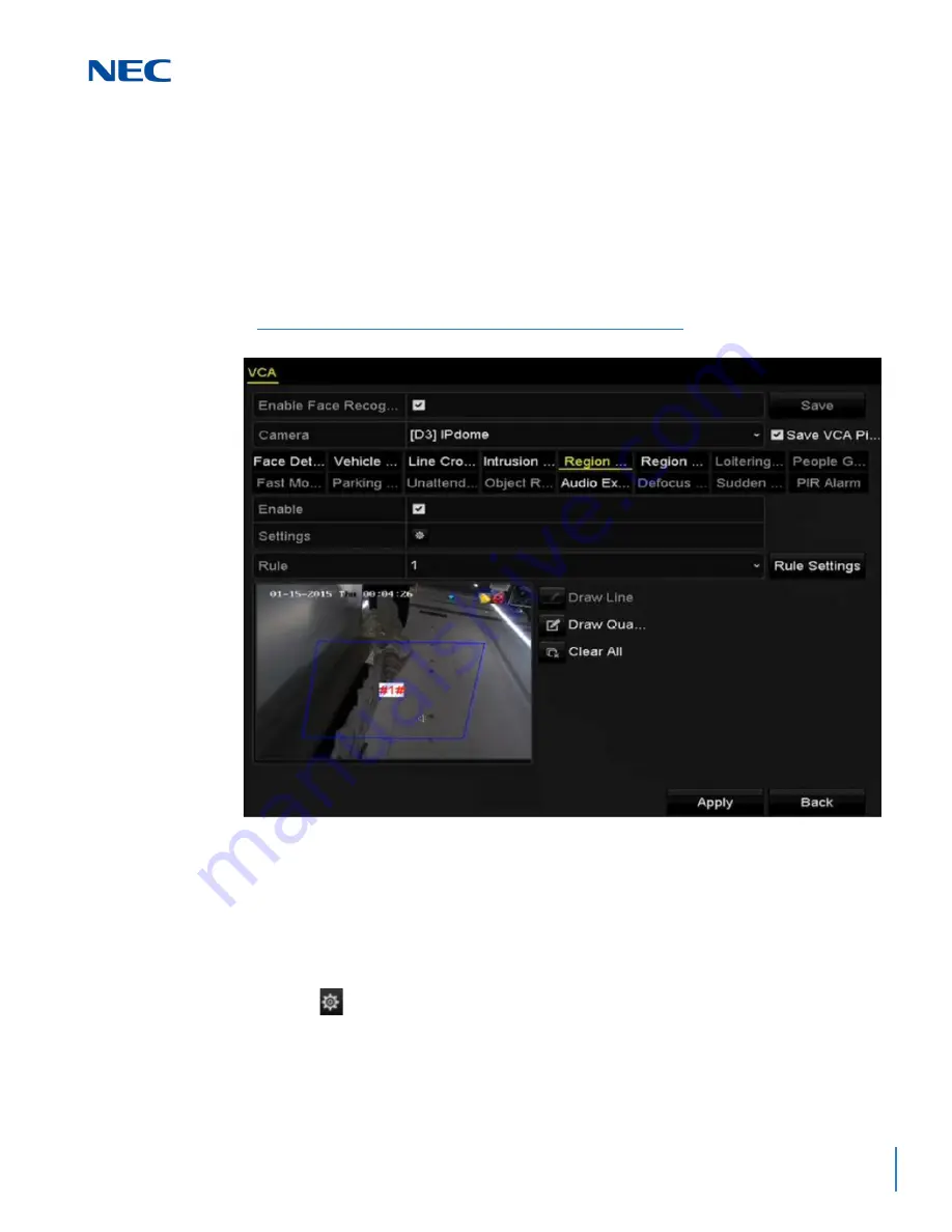
3.
Select the VCA detection type to
Region Entrance Detection
.
4.
Check the
Enable
checkbox to enable this function.
5.
Click
to configure the trigger channel, arming schedule and linkage actions for
the line crossing detection alarm.
6.
Click the
Rule Settings
button to set the sensitivity of the region entrance detection.
Sensitivity:
Range [0-100] The higher the value, the easier it is for the detection
alarm to be triggered.
Figure 9-8 Set Region Entrance Detection
Summary of Contents for NRS Expanded Series
Page 2: ......
Page 4: ......
Page 16: ...xii Table of Contents ISSUE 1 0 ...
Page 28: ...xxiv List of Figures and Tables ISSUE 1 0 ...
Page 32: ...Manual 2 NVR Configuration Guide Advanced for NRS Expanded Series ...
Page 36: ...Regulatory 4 NVR Configuration Guide Advanced for NRS Expanded Series ...
Page 84: ...ISSUE 1 0 3 10 Live View ...
Page 96: ...ISSUE 1 0 4 12 PTZ Controls ...
Page 168: ...ISSUE 1 0 8 16 Alarm Settings ...
Page 182: ...ISSUE 1 0 9 14 VCA Alarm ...
Page 190: ...ISSUE 1 0 10 8 VCA Search ...
Page 246: ...ISSUE 1 0 13 18 HDD Management ...
Page 250: ...ISSUE 1 0 14 4 Camera Settings ...
Page 280: ...Issue 1 0 A 12 Glossary and Troubleshooting ...


