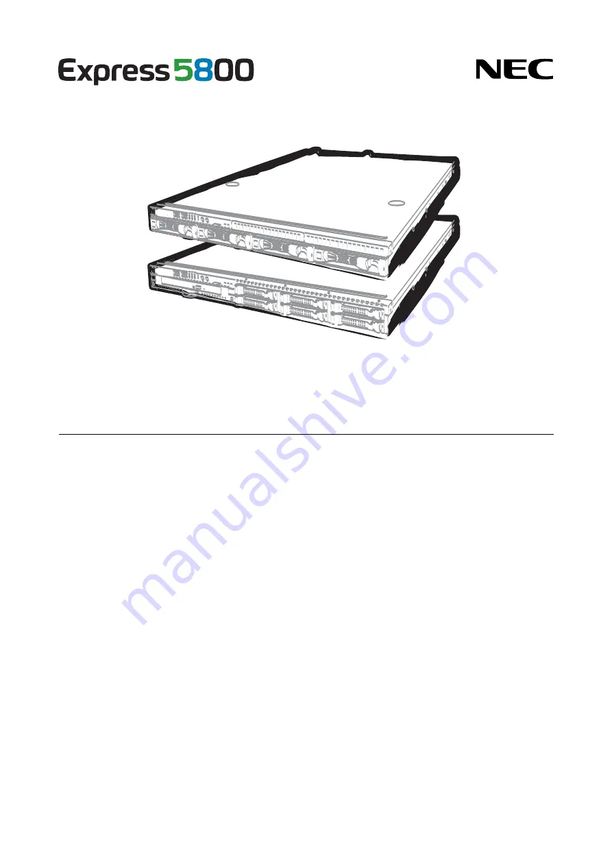
background image


NEC Express Server 
Express5800 Series 

10.101.03-101.01

July 2013, First Edition

© NEC Corporation 2013

Express5800/R110f-1E 

EXP283A/EXP284A 
User’s Guide 

Model Number:  N8100-1986F/1998F/1999F/2000F 


Chapter 1  General Description 

Chapter 2  Preparations 

Chapter 3  Setup 
 
Chapter 4  Appendix 

Summary of Contents for N8100-1998F

Page 1: ...101 03 101 01 July 2013 First Edition NEC Corporation 2013 Express5800 R110f 1E EXP283A EXP284A User s Guide Model Number N8100 1986F 1998F 1999F 2000F Chapter 1 General Description Chapter 2 Prepara...

Page 2: ...options connection of peripheral devices and ideal location for this server Chapter 3 Setup System BIOS configurations and summary of EXPRESSBUILDER PDF Chapter 4 Appendix Specifications and other in...

Page 3: ...cument and on warning labels 14 Safety notes 15 General 15 Rack installation 16 Power supply and power cord use 17 Installation relocation storage and connection 19 Cleaning and working with internal...

Page 4: ...on setting up a RAID System 71 1 11 Extra Battery for RAID Controller 73 1 11 1 Handling precautions 73 1 11 2 Installing N8103 154 extra battery for N8103 149 150 151 73 1 11 3 Installing flash backu...

Page 5: ...POST error messages 127 2 System BIOS Setup 128 2 1 Overview 128 2 2 Starting SETUP Utility 128 2 3 Description on On Screen Items and Key Usage 129 2 4 Cases that Require Setting Changes 131 3 EXPRE...

Page 6: ...cur Note Indicates items that must be confirmed when handling the server or operating software Tips Indicates information that is helpful to keep in mind when using this server Optical disk drives Thi...

Page 7: ...Windows Widnows Server 2012 Standard Widnows Server 2012 Datacenter Windows Server 2012 Windows Server 2012 Foundation Windows Server 2008 R2 Standard Windows Server 2008 R2 Windows Server 2008 R2 En...

Page 8: ...source code must retain the above copyright notice this list of conditions and the following disclaimer Redistributions in binary form must reproduce the above copyright notice this list of condition...

Page 9: ...Industrie Canada CAN ICES 3 A NMB 3 A CE Australia and New Zealand Statement This is a Class A product In domestic environment this product may cause radio interference in which case the user may be...

Page 10: ...Hazardous Substances in Electrical and Electronic Equipment adopted by Order 1057 of Cabinet of Ministers of Ukraine The Product is in conformity with the requirements of Technical Regulation on the...

Page 11: ...ess5800 R110f 1E User s Guide 11 1057 2 1 Pb 0 1 1000 2 Cd 0 01 100 3 Hg 0 1 1000 4 Cr6 0 1 1000 5 PBB 0 1 1000 6 PBDE 0 1 1000 1057 2 1 Pb 0 1 1000 2 Cd 0 01 100 3 Hg 0 1 1000 4 Cr6 0 1 1000 5 PBB 0...

Page 12: ...omissions please contact your retailer 5 Regardless of these 4 items NEC Corporation does not take responsibility for effects resulting from operations 6 The sample values used in this document are n...

Page 13: ...ls WARNING or CAUTION is used to indicate a degree of danger These terms are defined as follows WARNING Indicates there is a risk of death or serious personal injury CAUTION Indicates there is a risk...

Page 14: ...y the server Otherwise an electric shock or fire may be caused Do not touch the server with wet hand Otherwise an electric shock may be caused Do not touch the component specified by this symbol Other...

Page 15: ...tric shock Use a rack that conforms to the designated standard This server can be mounted onto a 19 inch rack that conforms to EIA standards Do not mount the server onto any rack that does not conform...

Page 16: ...ponents such as the door or rails When installing the door make sure that both upper and lower hinge pins are held in place Incomplete attachment may cause components to fall off as well as personal i...

Page 17: ...remove the covers and access of the components inside the system Plug into a proper power source Use a grounded outlet with the specified voltage Use of an outlet with a voltage other than that speci...

Page 18: ...wer cord Do not alter modify or repair the power cord Do not use a damaged power cord replace the damaged power cord with a power cord of the same standard For information on replacing the power cord...

Page 19: ...rning may cause the wiring on the printed wiring board to short circuit leading to fire If you have any questions contact the store where you purchased the product or a sales representative Do not ins...

Page 20: ...r Li ion battery some optional devices have a lithium NiMH or Li ion battery installed Do not remove the battery by yourself Placing a battery close to a fire or in the water may cause an explosion Wh...

Page 21: ...server during thunderstorms Do not touch any part of the server including the cables when a thunderstorm is approaching Also do not connect or disconnect any devices There may be a risk of electric sh...

Page 22: ...s label is either attached or printed on the component to draw attention from users to potential hazards involved in handling the server Do not remove or black out this label and keep it clean If no l...

Page 23: ...Precautions for Use Be Sure to Read Express5800 R110f 1E User s Guide 23 3 5 inch drive model...

Page 24: ...the server after power off Turn off the server and unplug the power cord before moving it Regularly clean the server to prevent various types of failure Refer to Chapter 1 Maintenance 2 Daily Maintena...

Page 25: ...ait for a sufficient period to use the server and components in the operating environment Reference Time effective at avoiding condensation in winter more than 10 C differences between the room temper...

Page 26: ...metal accessories such as a ring bracelet or wrist watch Handling of Components Keep the component in an anti static bag until you install it to the server Hold the component by the edges to avoid tou...

Page 27: ...from reflecting bright lights and to make the display contents easy to see Working without adjusting the display to a comfortable angle makes it difficult for you to maintain a proper posture and you...

Page 28: ...tures of this server and the name of each part 1 Introduction 2 Accessories Verify the condition of your server s accessories 3 Standard Features Check and maintain the server system by using the func...

Page 29: ...processor NEC s latest technology and architectures realize high power and high speed operation that cannot be matched by existing servers The server is designed with consideration of not only reliabi...

Page 30: ...ture use The tool used for removing slide rails outer rails EXPRESSBUILDER 1 Getting Started Cable ties for securing AC power cord SDR Update CD ROM Power cord 1 Documents are stored in EXPRESSBUILDER...

Page 31: ...ature Internal voltage monitoring feature RAID System Disk Array also available as an option Auto rebuild function hot swapping supported BIOS password feature The security lock that comes with Front...

Page 32: ...ce Three LAN ports one for management LAN Ready to use Hard disk drives can be installed with one touch setup which requires no cables hot swap supported Many built in Features El Torito Bootable CD R...

Page 33: ...rs temperatures fans voltage power supply doors and others Temperature Monitors the temperature inside of the chassis Fan Monitors the fans Voltage Monitors the voltage inside of the chassis Power sup...

Page 34: ...agement Use of NEC ESMPRO Manager and ExpressUpdate Agent allows you to manage versions of firmware and software as well as update them by applying update packages This function automatically updates...

Page 35: ...of system This LED lights green when the power is ON 4 Disk Access LED green amber This LED lights or flashes green when the internal hard disk drive or optical disk drive is being accessed The LED l...

Page 36: ...rive model 8 3 11 12 9 6 13 1 13 2 13 3 15 15 14 2 14 3 15 15 5 1 16 4 5 2 7 10 14 1 14 0 2 5 inch drive model x6 HDD model 8 3 11 12 9 6 16 14 0 15 14 2 15 14 4 13 1 13 2 13 3 14 1 15 14 3 15 14 5 5...

Page 37: ...n and off the UID LEDs provided at the front and rear of the server Pressing the switch once turns on the UID LED and pressing once more turns off the LED Commands from the software also cause it to t...

Page 38: ...Display connector The connector to connect a display 7 DC Power LED green During BMC initialization this LED lights amber This LED lights green when the power is ON 8 USB connectors These connectors...

Page 39: ...4 Names and Functions of Parts Express5800 R110f 1E User s Guide 39 Chapter 1 General Description 4 4 External View 1 Top cover 2 Release button 2 1 1 2 3 5 inch drive model 2 5 inch drive model...

Page 40: ...oard 6 PCI riser card 7 Processor attached under the heat sink 8 Cooling fan 1 BPB_FAN1 2 BPB_FAN3 3 BPB_FAN5 4 BPB_FAN7 5 BPB_FAN9 6 BPB_FAN11 9 2 5 inch hard disk drive bay The sequential numbers in...

Page 41: ...hed under the heat sink 8 Cooling fan 1 BPB_FAN1 BPB_FAN2 2 BPB_FAN3 BPB_FAN4 3 BPB_FAN5 BPB_FAN6 4 BPB_FAN7 BPB_FAN8 5 BPB_FAN9 BPB_FAN10 6 BPB_FAN11 BPB_FAN12 9 2 5 inch hard disk drive bay The sequ...

Page 42: ...d 7 Processor attached under the heat sink 8 Cooling fan 1 BPB_FAN1 2 BPB_FAN3 3 BPB_FAN5 4 BPB_FAN7 5 BPB_FAN9 6 BPB_FAN11 9 3 5 inch hard disk drive bay The sequential numbers indicate the correspon...

Page 43: ...nder the heat sink 8 Cooling fan 1 BPB_FAN1 BPB_FAN2 2 BPB_FAN3 BPB_FAN4 3 BPB_FAN5 BPB_FAN6 4 BPB_FAN7 BPB_FAN8 5 BPB_FAN9 BPB_FAN10 6 BPB_FAN11 BPB_FAN12 9 3 5 inch hard disk drive bay The sequentia...

Page 44: ...connector SPI flash memory has been installed where BIOS and BMC configuration data is stored Move it when replacing MB to keep using the data 16 Serial port COM B connector 17 Internal Flash Memory c...

Page 45: ...ror logs to check the causes of failures Status LED pattern Explanation Solution On green Normal state Memory is in a degraded state An uncorrectable memory error has often occurred Flashing green Ope...

Page 46: ...are normal contact your sales representative A temperature warning was detected Check the internal fan for dusts Also check if the fan unit is properly connected If the LED indication does not change...

Page 47: ...ps When Logical Drives RAID 1 5 6 10 50 and 60 are configured in the RAID System the system can continue to operate even if one hard disk drive 2 drives in the case of RAID 6 or RAID 60 failed However...

Page 48: ...e LAN connector is transmitting or receiving data If the LED does not turn on in LINK state check the cable or connection SPEED LED This LED indicates which network interface is used The two LAN conne...

Page 49: ...This chapter describes preparations for using this server 1 Installing Internal Optional Devices You can skip this section if you did not purchase any optional devices 2 Installation and Connection Y...

Page 50: ...od 1 1 Safety Precautions Be sure to observe the following precautions to install and remove optional devices properly and safely WARNING Be sure to observe the following precautions to use the server...

Page 51: ...ve any kind of metal accessories such as a ring bracelet or wrist watch Handling of Components Keep the component in an anti static bag until you install it to the server Hold the component by the edg...

Page 52: ...a rack use the UID switch to identify the target server Refer to Chapter 2 1 4 Confirming Servers UID Switch 2 Remove the front bezel if applicable Refer to Chapter 2 1 5 Removing the Front Bezel 3 I...

Page 53: ...Drive 8 Connect cables Refer to Chapter 2 1 10 1 Connecting cables 9 Attach the top cover Refer to Chapter 2 1 19 Attaching the Top Cover 10 Mount the server onto the rack Refer to Chapter 2 2 1 2 1...

Page 54: ...elps you to identify the target server When the server is working or before you turn the server off or disconnect a cable from the server be sure to identify the target server by using the UID switch...

Page 55: ...ont bezel side while pressing it lightly to release the lock 2 Hold the right end of the front bezel carefully to pull it toward you 3 Slide the front bezel to the left a little to release the tab fro...

Page 56: ...he Internal Flash Memory in the following procedure 1 Refer to steps 1 to 4 in Chapter 2 1 3 Overview of Installation and Removal for preparations 2 Attach the Internal Flash Memory and fix it with th...

Page 57: ...M Kit 1 8 1 Installation Install the TPM Kit in accordance with the following procedure Note The TPM kit once installed cannot be removed 1 Refer to steps 1 to 6 in Chapter 2 1 3 Overview of Installat...

Page 58: ...te of the memory is twice that of a non interleaved memory system 1 9 1 Maximum supported memory size The maximum available memory size on the server depends on the architecture x86 architecture and O...

Page 59: ...hem in pairs The two DIMMs installed together must be of the same specifications and memory size Install the pairs as DIMM 1 and DIMM 2 or DIMM 3 and DIMM 4 the installation order between the pairs do...

Page 60: ...e server and turn it on 6 Confirm that no error messages are displayed in POST screen If any error messages are displayed refer to Chapter 3 1 POST Error Message in Maintenance Guide 7 Run the SETUP u...

Page 61: ...g it up straight 5 Continue to install or remove internal optional devices mount and connect the server and turn it on 6 Confirm that no error messages are displayed on POST If any error message is di...

Page 62: ...backup the Hard Disk Drive before installing the RAID Controller and configuring the RAID System Note In the RAID System use Hard Disk Drives that have the same specifications capacity rotational spe...

Page 63: ...using the on board SATA controller Backplane for 3 5 inch Hard Disk Drive J3 Backplane for 2 5 inch Hard Disk Drive J3 After that configure the RAID System by using the LSI Software RAID Configuration...

Page 64: ...nal RAID Controller start the BIOS Setup utility select PCI Configuration from the Advanced menu and then make sure that the parameter of PCI Slot xx ROM xx is PCI slot number is set to Enabled Import...

Page 65: ...ecting a RAID Controller set the boot priority to 8th or higher in the Boot menu of the BIOS Setup utility If the setting is 9th or lower the configuration menu for RAID Controllers cannot be launched...

Page 66: ...oller for a 3 5 inch drive model You need to prepare the internal SAS SATA cable K410 288 00 which is separately available Connect the P0 to P3 connectors of the internal SAS SATA cable K410 288 00 to...

Page 67: ...410 240 00 to the SATA0 to SATA3 connectors on the backplane respectively Connect pin 1 indicated by the triangle of the S1 connector of the internal SAS SATA cable K410 240 00 to pin 1 indicated by t...

Page 68: ...ves You need to prepare the internal SAS SATA cable K410 289 00 which is separately available Connect the P0 to P3 connectors of the internal SAS SATA cable K410 289 00 to the SATA2 to SATA5 connector...

Page 69: ...nnect pin 1 indicated by the triangle of the S1 connector of the internal SAS SATA cable K410 240 00 to pin 1 indicated by the bold line of the SGPIO1 connector on the backplane Connect pin 1 indicate...

Page 70: ...dicated by the triangle of the S1 connector of the internal SAS SATA cable K410 240 00 to pin 1 indicated by the bold line of the SGPIO1 connector on the backplane Connect pin 1 indicated by the trian...

Page 71: ...isk Drives or SSDs that have the same capacity and rotational speed If you intend to install the OS to the RAID System the process from RAID configuration to OS installation can be easily completed by...

Page 72: ...Preparations The insert position number displayed on the server 3 5 inch drive model 2 5 inch drive model 1 to 6 drives slot Slot 2 Slot 0 Slot 1 Slot 3 Slot 4 Slot 5 2 5 inch drive model 1 to 8 drive...

Page 73: ...estroyed Use the extra battery that supports the RAID Controller used The extra battery is a very delicate electronic device Before installation touch the metal frame part of the server to discharge t...

Page 74: ...e riser card into the slot of the motherboard and fix the riser card with the screw which you removed in step 5 Position the terminal part of the riser card in the slot of the motherboard and then sec...

Page 75: ...connector and insert the connector straight and securely 11 Attach the extra battery to the battery bracket by using three screws The installation position of the extra battery is PCI 1B side 12 Atta...

Page 76: ...to remove the top cover 3 Connect FBU control cable 600 mm that comes with the N8103 152 RAID Controller 4 Remove the screw securing the riser card Hold the both sides of the card and lift it straigh...

Page 77: ...to the battery bracket by using one screw The installation position of the flash backup unit is the PCI 1B side 10 Then connect FBU control cable 600 to flash backup unit 11 Attach the bracket you rem...

Page 78: ...es with extra battery to RAID Controller When connecting the cable orient the cable so that its marking will fit the connector 4 Remove the screw securing the riser card Hold the both sides of the car...

Page 79: ...ference connect the battery control cable to the battery pack When connecting the cable check the orientation of the connector and connect straight 11 Attach the extra battery to the battery bracket b...

Page 80: ...Installing Internal Optional Devices Express5800 R110f 1E User s Guide 80 Chapter 2 Preparations 1 11 5 Removal For removing the extra battery for the RAID Controller reverse the installation procedur...

Page 81: ...touch the PCI card terminals or parts with bare hand or place the PCI card directly on the desk For detailed information on static electricity refer to Chapter 2 1 2 Anti static Measures Note The com...

Page 82: ...e number and function number shown in the table below PCI device PCI bus number Device number Function number Onboard NIC1 39h 0 0 Onboard NIC2 39h 0 1 Slot 1A 1h 0 Slot 1B 2h 0 Set Disabled for the o...

Page 83: ...pplied with the card Tips Different cards mounted on the same bus operate at the lower frequency When the operation performance of a PCI card is higher than the PCI slot on the server the PCI card ope...

Page 84: ...cting internal disks The RAID cache can be backed up by using the flash backup unit that comes with N8103 167 N8103 160 RAID Controller 1GB RAID 0 1 5 6 Card performance PCI EXPRESS 2 0 x8 c c For con...

Page 85: ...agePathSavior supports redundant bus of FC Only one port per system is used for LAN Teaming bonding with LAN is not available N8117 01A Additional RS 232C connector kit c c For additional serial RS 23...

Page 86: ...r 2 1 3 Overview of Installation and Removal for preparations 2 Refer to Chapter 2 1 6 Removing the Top Cover to remove the top cover 3 Remove the screw securing the riser card Hold the both ends of t...

Page 87: ...he riser card to the server 8 Connect the riser card to the mother board slot and fix the card with the screw you removed in step 3 When connecting the card position the terminal part of the card to t...

Page 88: ...2 1 2 Anti static Measures Note When installing an optional RAID Controller start the BIOS Setup utility select PCI Configuration from the Advanced menu and then make sure that the parameter of PCI Sl...

Page 89: ...re a 3 5 inch drive model 1 Refer to Chapter 2 1 3 Overview of Installation and Removal for preparations 2 Refer to Chapter 2 1 6 Removing the Top Cover to remove the top cover 3 Unscrew one of the sc...

Page 90: ...and the two screws securing the optical disk drive tray and pull the tray out 4 Remove the optical disk drive cover Important Keep the screw and dummy tray in the optical disk drive for future use 5 U...

Page 91: ...e 1 14 Redundant Fan Replace the standard cooling fan with an optional redundant fan to make redundant fan configuration 1 14 1 Replacing the standard fan unit with redundant fan unit 1 Replacing the...

Page 92: ...arrows that indicate the air flow 6 Connect the fan cables to the backplane Make sure that the fan cables are not caught in the top cover fan or chassis FAN11 FAN12 FAN9 FAN10 FAN7 FAN8 FAN5 FAN6 FAN3...

Page 93: ...hapter 2 Preparations 7 Change the setting of jumper pins on the motherboard as shown in the figure below Important Do not change the setting of other jumper pins Doing so may cause malfunction or fai...

Page 94: ...be required 1 15 1 Installation Install a Hard Disk Drive by using the following procedure Follow the same installation procedure for other bays Important In the RAID System build a Disk Array using H...

Page 95: ...nds 6 Slowly close the handle The tray is locked making a clicking sound Important Do not get your finger caught between the handle and the tray Note When you push the drive into the bay confirm the h...

Page 96: ...1 3 Overview of Installation and Removal for preparations 2 Push the lever to unlock and open the handle 3 Hold the handle and tray firmly and pull the Hard Disk Drive out 4 If you intend to use the s...

Page 97: ...50 The disk is automatically rebuilt when hot swapping replacing a disk while the power is on a failed Hard Disk Drive During the auto rebuild the DISK LED on the Hard Disk Drive flashes green and amb...

Page 98: ...rive Hard Disk Drives with different types of interfaces or different rotational speeds cannot be installed together Hard Disk Drives and SSD can be installed together However you cannot install them...

Page 99: ...removed simply by removing the front bezel 1 Refer to Chapter 2 1 3 Overview of Installation and Removal for preparations 2 Locate the bay where you install the Hard Disk Drive The server provides six...

Page 100: ...the handle The tray is locked making a clicking sound Important Do not get your finger caught between the handle and the tray Note When you push the drive into the bay confirm the handle got hooked on...

Page 101: ...pter 2 1 3 Overview of Installation and Removal for preparations 2 Push the lever to unlock and open the handle 3 Hold the tray firmly and pull out the Hard Disk Drive 4 If you intend to use the serve...

Page 102: ...The disk is automatically rebuilt when hot swapping replacing a disk while the power on a failed Hard Disk Drive During auto rebuild the DISK LED on the Hard Disk Drive flashes green and amber alterna...

Page 103: ...ch HDD cage is installed 1 17 1 Installation Install the extra 2 5 inch HDD cage by using the following procedure 1 Refer to Chapter 2 1 3 Overview of Installation and Removal for preparations 2 Refer...

Page 104: ...hard disk drive When six hard disk drives are connected 2 3 default When eight hard disk drives are connected 1 2 7 Change the cable connection between the optional RAID Controller and the backplane f...

Page 105: ...Replacing the standard power supply unit with redundant power supply unit 1 See Chapter 2 1 3 Overview of Installation and Removal for preparations 2 Remove the right inner rail when viewed from the...

Page 106: ...for the redundant power supply unit with four screws two flat head screws and two countersunk screws The bracket is provided with the redundant power supply unit 8 Mount the power cage to the chassis...

Page 107: ...pter 2 Preparations 10 Insert the two redundant power supply units into two slots in the power cage 11 Attach the cable tie that comes with the redundant power supply unit to the handle of the redunda...

Page 108: ...mper pins on the motherboard as shown in the figure below Important Do not change the setting of other jumper pins Doing so may cause malfunction or failure of the server 14 Update SDR by using SDR Up...

Page 109: ...ck the release button If the cover is locked the button is raised If the button stays depressed slide the cover backward again If that does not work remove the top cover and try again 1 20 Attaching t...

Page 110: ...nly in the specified environment Do not connect the ground wire to a gas pipe CAUTION Be sure to observe the following precautions to use the server safely Failure to observe the precautions may cause...

Page 111: ...one etc exist Place where the air or dust includes components accelerating corrosion ex sulfur sodium chloride or conductive metals Place where chemicals may be accidentally sprayed over Place where a...

Page 112: ...cautions to use the server safely Failure to observe the precautions may cause burns injury and property damage For details refer to Safety precautions in Precautions for Use Do not drop Do not leave...

Page 113: ...to prevent falling off during transportation Remove the tape before mounting it to the rack Removing rail assemblies 1 Remove the slide rails from left and right sides of the server 2 While pressing...

Page 114: ...lowing the same procedure Make sure that the rail assembly is installed at the same height as the other slide rail already installed Important Confirm that the rails are securely locked so that they w...

Page 115: ...lock buttons located on either side of the front of the server 4 Because there are stoppers the server will come to a stop halfway Press and hold the stoppers on the rails and pull the server out of t...

Page 116: ...nstallation and Connection Express5800 R110f 1E User s Guide 116 Chapter 2 Preparations 6 When removing the rail from the rack pull the rail in the direction of the arrows while pressing the lever Lev...

Page 117: ...y using the following procedure 1 Refer to Chapter 2 2 1 2 2 Removal procedure to remove the server from the rack 2 Prepare the designated tool to remove slide rail outer rail that comes with the serv...

Page 118: ...5 Remove the rail from the rack while it is being unlocked 6 Insert the tool into the square hole at the rear of the rail in the direction described As shown in the image on the right rotate the tool...

Page 119: ...setting ask a service technician or a system engineer of your maintenance service company WARNING Be sure to observe the following precautions to use the server safety Failure to observe the precautio...

Page 120: ...wer cord to a circuit braker of up to 15 A To prevent power cord from disconnecting secure the power cord with the provided cable tie Ports for data transmission 1000BASE T 100BASE TX 10BASE T Device...

Page 121: ...and Some devices from a third party cannot be used with the server Fix the power cord or interface cable with cable ties Organize cables so that they will not contact the door of the rack or the guide...

Page 122: ...UPS the BIOS settings may need to be changed in order to link the server with the power supply from the UPS To change the settings select Server and then AC LINK in the BIOS setup utility and change...

Page 123: ...ettings by following the instructions in this section 3 EXPRESSSCOPE Engine 3 EXPRESSSCOPE Engine 3 provides useful features through the Baseboard Management Controller BMC 4 EXPRESSBUILDER EXPRESSBUI...

Page 124: ...the display monitor and the server Note If the power cord is connected to power control system such as an Uninterruptible Power Supply UPS make sure that the power control system is turned on 2 Remov...

Page 125: ...after you installed or removed an optional PCI board or moved it to another slot may display the message that indicates incorrect board configuration and suspend POST In such a case press the F1 key...

Page 126: ...VD ROM is set on the drive with the boot priority of CD DVD ROM is set to higher than Hard Disk Drive 6 If a controller which has its dedicated BIOS such as a SAS controller board is installed a messa...

Page 127: ...s an error it displays an error message on the screen or beeps for some errors For descriptions of error messages causes and countermeasures refer to Maintenance Guide Note Take notes on the messages...

Page 128: ...fter a while the following message will be displayed on the lower left of the screen Press F2 SETUP F3 Internal Flash Memory F4 ROM Utility F12 Network If you press the F2 key at this time SETUP runs...

Page 129: ...f the selected item You cannot use this key when a menu which has on the left is selected Enter key Press this key to confirm the selected parameter Esc key Pressing this key takes you to the previous...

Page 130: ...F3 key If you press this key the following window appears If you select Yes restore the parameters of the currently selected item to the default setting This might be different from the parameters con...

Page 131: ...is PCI slot number of the RAID Controller Advanced PCI Configuration PCI Device Controller and Option ROM Settings PCI Slot n Option ROM Enabled n Slot number in the PCI device except for the boot dev...

Page 132: ...LINK Stay off Password If you have set a password a message prompt you to enter password will be displayed from the next time Enter password You can attempt password entry up to 3 times If you entere...

Page 133: ...B mass storage device Remote FD Remote CD DVD Remote USB Memory or Virtual Flash is virtually connected If the server runs on Windows Server 2008 R2 this feature does not support the video resolution...

Page 134: ...owing message appears on the lower left of the screen Press F2 SETUP F3 Internal Flash Memory F4 ROM Utility F12 Network 2 If you press the F4 key at this time ROM utility starts upon completion of PO...

Page 135: ...ress Subnet Mask Tips If Shared BMC LAN is enabled Web feature remote media KVM feature or command line interface feature may be interrupted In this case wait for a while and connect with network agai...

Page 136: ...ture select Tool menu in the menu after boot Storage of documents Stores various documents including User s Guide Installation Guide and Maintenance Guide Documents and some software components are no...

Page 137: ...ftware Components Express5800 R110f 1E User s Guide 137 Chapter 3 Setup 5 Installing Software Components Continue to install software components such as OS Refer to the instructions below Installation...

Page 138: ...he server is connected to a UPS refer to the documentation supplied with the UPS or the documentation for the application controlling the UPS 1 Shut down the OS 2 The server automatically turns off af...

Page 139: ...Express5800 R110f 1E User s Guide 139 NEC Express5800 Series Express5800 R110f 1E Appendix 1 Specifications 2 Interrupt Lines...

Page 140: ...Supported Interface level RAID System SATA 6 Gb s RAID 0 1 10 standard RAID 5 6 50 optional SAS 6 Gb s RAID 0 1 5 6 10 50 optional Optical disk drive Internal external drive optional 1 Auxiliary stora...

Page 141: ...r as standard Power code Installed OS Supported OSs Microsoft Windows Server 2008 Standard RTM SP2 or later Microsoft Windows Server 2008 Enterprise RTM SP2 or later Microsoft Windows Server 2008 R2 S...

Page 142: ...RAID System SATA 6 Gb s RAID 0 1 10 standard RAID 5 6 50 optional SAS 6 Gb s RAID 0 1 5 6 10 50 optional Optical disk drive Internal external drive optional 1 Auxiliary storage FDD Option Flash FDD 1...

Page 143: ...s standard Power code Installed OS Supported OSs Microsoft Windows Server 2008 Standard RTM SP2 or later Microsoft Windows Server 2008 Enterprise RTM SP2 or later Microsoft Windows Server 2008 R2 Stan...

Page 144: ...ve Internal external drive optional 2 FDD Option Flash FDD 1 44MB 3 Auxiliary storage Additional bay None Additional slots Supported slots 1x PCI EXPRESS 3 0 x16 lanes x16 sockets 1x PCI EXPRESS 2 0 x...

Page 145: ...Server 2008 Enterprise RTM SP2 or later Microsoft Windows Server 2008 R2 Standard Microsoft Windows Server 2008 R2 Enterprise Microsoft Windows Server 2012 Standard Microsoft Windows Server 2012 Datac...

Page 146: ...ernal drive optional 2 FDD Option Flash FDD 1 44MB 3 Auxiliary storage Additional bay None Additional slots Supported slots 1x PCI EXPRESS 3 0 x16 lanes x16 sockets 1x PCI EXPRESS 2 0 x4 lanes x8 sock...

Page 147: ...Server 2008 Enterprise RTM SP2 or later Microsoft Windows Server 2008 R2 Standard Microsoft Windows Server 2008 R2 Enterprise Microsoft Windows Server 2012 Standard Microsoft Windows Server 2012 Datac...

Page 148: ...eference when you add optional devices Interrupt lines As factory settings interrupt lines are assigned as follows IRQ Peripheral Device Controller IRQ Peripheral Device Controller 0 System timer 8 Re...

Reviews: