background image

English-6

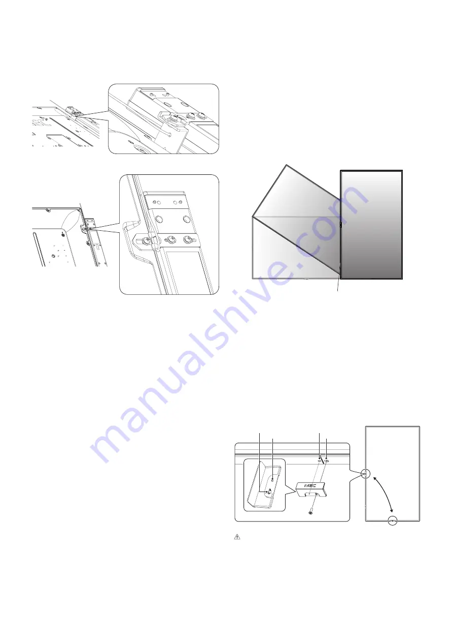
Installing a wire to a monitor with installed speakers 
(Landscape position only)

Please use speaker mounting parts to install a wire to the 
monitor.
Optional speaker is installed on the rear of the LCD monitor:

Optional speaker is installed on the side of the LCD monitor:

Mounting location 

•฀ The฀ceiling฀and฀wall฀must฀be฀strong฀enough฀to฀support฀the฀

monitor and mounting accessories.

•฀ DO฀NOT฀install฀in฀locations฀where฀a฀door฀or฀gate฀can฀hit฀

the unit. 

•฀ DO฀NOT฀install฀in฀areas฀where฀the฀unit฀will฀be฀subjected฀

to strong vibrations and dust.

•฀

DO NOT install the monitor next to a location where the 
main power supply is fed into the building.

•฀

DO NOT install the monitor in a location where people 
can easily grab and hang onto the unit or the mounting 
equipment.

•฀

Allow for adequate ventilation or provide air conditioning 
around the monitor, so that heat can properly dissipate 
away from the monitor and from the mounting equipment.

Mounting on ceilings

•฀ Ensure฀that฀the฀ceiling฀is฀sturdy฀enough฀to฀support฀the฀

weight of the unit and the mounting equipment over time, 
against earthquakes, unexpected vibrations, and other 
external forces.

•฀ Be฀sure฀the฀unit฀is฀mounted฀to฀a฀solid฀structure฀within฀

the ceiling, such as a support beam. Secure the monitor 
using bolts, spring lock washers, washer and nut.

•฀ DO฀NOT฀mount฀to฀areas฀that฀have฀no฀supporting฀internal฀

structure. DO NOT use wood screws or anchor screws for 
mounting. DO NOT mount the unit to ceiling or to hanging 
fixtures.

Maintenance 

•฀ Periodically฀check฀for฀loose฀screws,฀gaps,฀distortions,฀

or other problems that may occur with the mounting 
equipment. If a problem is detected, please refer to 
qualified personnel for service.

•฀ Regularly฀check฀the฀mounting฀location฀for฀signs฀of฀

damage or weakness that may occur over time. 

Orientation 

•฀ When฀using฀the฀monitor฀in฀the฀portrait฀position,฀it฀should฀

be rotated clockwise so that the left side is moved to 
the top, right side is moved to the bottom. This will allow 
for proper ventilation and will extend the lifetime of the 
monitor. Improper ventilation may shorten the lifetime of 
the monitor.

LED Indicator

Changing NEC logo ornament position

When using the monitor in the portrait position, the NEC logo 
ornament position can be changed.

Removing the logo ornament: unscrew the installed screw 
then take off the logo ornament.

Attaching the logo ornament: adjust the protrusions inside of 
the logo ornament into the protrusion hole on the bezel. Make 
sure the hole for the screw on the logo ornament and the 
hole for the screw on the bezel are aligned. Install the logo 
ornament with the screw, which is used for installing the logo 
ornament.
(Recommended Fasten Force: 30-40N

cm).

Inside of NEC logo ornament

Screw hole

Screw hole

Protrusion

Protrusion hole

 CAUTION:

   Do not use any other screw to install the logo 

ornament.

Summary of Contents for MultiSync V554

Page 1: ...ltiSync V404 MultiSync P484 MultiSync V484 MultiSync P554 MultiSync V554 Please find your model name in the label on the rear side of the monitor Large Format Display User s Manual MODEL P404 V404 P48...

Page 2: ...ttings English 24 NETWORK OTHER SETTINGS English 25 Using SHARED SD card SETTINGS English 26 Using CONTENTS COPY English 27 Using Emergency contents English 27 Information OSD English 27 Picture Mode...

Page 3: ...e to radio or television reception which can be determined by turning the equipment off and on the user is encouraged to try to correct the interference by one or more of the following measures Reorie...

Page 4: ...accordance with the table below If a power cord is not supplied with this equipment please contact NEC For all other cases please use the power cord with the plug style that matches the power socket w...

Page 5: ...s at the rear side of the cabinet at least once a year to remove dirt and dust When using a LAN cable do not connect to a peripheral device with wiring that might have excessive voltage Do not use the...

Page 6: ...ration or discoloration on the LCD panel surface Cleaning the Cabinet Unplug the power supply Gently wipe the cabinet with a soft cloth To clean the cabinet dampen the cloth with a neutral detergent a...

Page 7: ...0 635N cm Bracket hole should be under 8 5 mm Prior to mounting inspect the installation location to ensure that it is strong enough to support the weight of the unit so that the unit will be safe fro...

Page 8: ...mount to areas that have no supporting internal structure DO NOT use wood screws or anchor screws for mounting DO NOT mount the unit to ceiling or to hanging fixtures Maintenance Periodically check f...

Page 9: ...the monitor face down on the soft cloth NOTE Be sure to place the monitor on a flat and adequate space 3 Remove the attached slot cover by unscrewing the installed screws Figure 1 Figure 1 4 Insert t...

Page 10: ...re 3 Please adjust the pipe to the lines Figure 3 P554 V554 High Low P484 V484 High Low P404 V404 High Low Pipe Adjust the pipe to a line 2 Please install the stand pole and the pipe with included scr...

Page 11: ...ment items within the OSD menu G Down Button Activates the OSD menu when the OSD menu is turned off Acts as button to move the highlighted area down to select adjustment items within the OSD menu H Me...

Page 12: ...croSD Card Slot Insert a microSD memory card To use the Media player please connect a microSD memory card to this port See page 22 To install the microSD card slot cover please refer to Installing mic...

Page 13: ...bles equipment For products visit Kensington s website Rating Label Intelligent Wireless Data Sensor Sensor for wireless communication of monitor for information and settings Option Speaker Mounting H...

Page 14: ...el within the OSD menu settings Small screen which adjusted PIP mode moves left or right and increases or decreases the size L SET POINT ZOOM Button SET When OSD is shown this button acts as set butto...

Page 15: ...F Button Toggle switches between ON and OFF MODE Button Selects a mode from PIP picture in picture or PBP picture by picture CHANGE Button Swaps images between two pictures PICTURE ASPECT Button Selec...

Page 16: ...table before laying the monitor face down 2 Install the remote control batteries The remote control is powered by two 1 5V AAA batteries To install or replace batteries A Press and slide to open the...

Page 17: ...ch on the power of the monitor first 7 Operate the attached external equipment Show the signal on the screen from the desired input source 8 Adjust the sound Make volume adjustments when required 9 Ad...

Page 18: ...udio signal Multiple monitors that are daisy chained have a limit to the connectable monitors 1 The device connected to USB2 can control the device connected to USB1 Connected equipment Connecting ter...

Page 19: ...No No Compressed image Only HBR2 is set Input TMDS signals conforming to DVI standards To maintain the image reproduction quality use a cable that conforms to DVI standards Connecting a Player or Comp...

Page 20: ...unction may not be working In this case please check user s manual of your computer or device or contact your supplier for detailed information Before turning off the main power switch of the monitor...

Page 21: ...monitor power indicator will turn blue while powered on NOTE The Main Power switch must be in the ON position in order to power up the monitor using the remote control or the Power button Main Power S...

Page 22: ...wing amber The monitor has been past a certain amount of time with network signal input and no AV signal input which you set Blinking amber No AV signal input has been detected by the monitor during t...

Page 23: ...e displayed in the Sorted order NOTE Only 1 USB storage device can be recognized by the viewer A window will appear when you press the control panel buttons while the Media Player is active You can se...

Page 24: ...20 Horizontal x 1080 Vertical Compatible microSD memory card Format a microSD memory card in the FAT32 format or FAT16 format Refer to the computer s instruction user s manual or Help file on how to f...

Page 25: ...e files can be displayed using either icons or thumbnails in the Media Player Icon display RETURN Goes back one subsequent level higher PAGE UP Displays a list of the previous files PAGE DOWN Displays...

Page 26: ...or MANUAL INTERVAL Sets interval time REPEAT Check the check box to repeat slideshow AUDIO FILE Selects an audio file BGM Check the check box to enable BGM PLAY END SCREEN Selects a setting for when t...

Page 27: ...lling the monitor Menu Function ENABLE Check the checkbox to enable SHARED FOLDER SETTINGS SHARED FOLDER Set the IP address of the network shared folder location that contains the files for copying to...

Page 28: ...cedure 1 Open the Monitor LAN control of the network connected monitor then select SD CARD VIEWER 2 Select SEARCH to display the IP ADDRESS of the currently connected monitor and all compatible monito...

Page 29: ...splayed if the microSD memory card storage capacity is not enough to copy selected folders When contents copy has occurred previous data that was saved in the microSD memory card is deleted Only devic...

Page 30: ...pace used for the Internet Windows operating systems and digital cameras Recommended setting for general color management Adobe RGB SIM Provides a standard color space used in high end graphics applic...

Page 31: ...ate the view of those with a color vision deficiency It is not their actual view The simulation is a reproduction of those with a strong color vision mode of type P type D or type T People with a slig...

Page 32: ...n board you are using 2 This input is available when the optional Raspberry Pi Compute Module Interface Board and Raspberry Pi Compute Module are installed For VGA YPbYr VIDEO MP STANDARD CINEMA CUSTO...

Page 33: ...IFORMITY OFF METAMERISM ON OFF COLORCONTROL R 0 Y 0 G 0 C 0 B 0 M 0 Goto Adjustment Select Return Close C MODULE MULTI INPUT OPTION Input source Main Menu Icons Main Menu Item Sub Menu Key Guide Adjus...

Page 34: ...COM SIM DICOM GSDF curve simulated for LCD type PROGRAMMABLE1 2 3 A programmable gamma curve can be loaded using optional NEC software COLOR 2 COLOR Adjusts the color depth of the screen Press or to a...

Page 35: ...MAGE FLIP and then start IMAGE FLIP When the ASPECT is DYNAMIC or ZOOM the image will be changed to FULL image before TILE MATRIX then start to TILE MATRIX After TILE MATRIX the ASPECT will be returne...

Page 36: ...layed clearly but it makes brightness unstable due to the wide gap of contrast variation ROTATION Shows the inverse image right left up down or rotation Press or to select NOTE This function is not av...

Page 37: ...se set ON or OFF for each schedule TIME Set the schedule operation time If there is no specific time for the schedule set INPUT Set the input signal for the schedule To keep the input signal that is a...

Page 38: ...Active Picture NOTE This function depends on MULTI PICTURE setting ACTIVE FRAME The active picture is shown within a red frame INPUT SELECT 1 2 3 Selects the Multi Picture input Press the button or bu...

Page 39: ...s the kind of DVI D equipment which is connected to the DVI input Select DVI HD when a DVD player or computer equipment is connected which requires HDCP authentication Select DVI PC when computer equi...

Page 40: ...d captioning NOTE This function is released if the following function is activated MULTI PICTURE MODE TEXT TICKER PORTRAIT in OSD ROTATION TILE MATRIX SCREEN SAVER STILL POINT ZOOM SUPER in INPUT CHAN...

Page 41: ...n SET is selected AUTO ID IP SETTING window is shown Do not connect network devices between the monitors connected with LAN SETTING ITEM Select an item from MONITOR ID IP ADDRESS and ID and IP MONITOR...

Page 42: ...kground color of the Media Player window is also changed POWER ON DELAY Adjusts the delay time between being in standby mode and entering power on mode DELAY TIME POWER ON DELAY can be set between 0 a...

Page 43: ...ked The unselected buttons are locked When LOCK is selected all INPUT buttons are locked CHANNEL To lock channel buttons on the remote control select it to LOCK then press ACTIVE channel CH ZOOM butto...

Page 44: ...is high HUMAN SENSING 2 HUMAN SENSING has three settings NOTE POWER SAVE is disabled when AUTO OFF or CUSTOM is selected in HUMAN SENSING HUMAN SENSING is released if INPUT DETECT is set while HUMAN...

Page 45: ...shown When search has been completed or failed the SEARCH DEVICE is set to NO automatically To retry the SEARCH DEVICE set it to YES again After detecting HDMI CEC devices you can switch the device i...

Page 46: ...he related settings Please do not change settings in COMPUTE MODULE yourself POWER POWER SUPPLY Controls power to the Compute Module AUTO POWER ON When set to Enable power to the Compute Module will b...

Page 47: ...on the screen Unlike CRT monitors LCD monitors image persistence is not permanent but a still image being displayed for a long period of time should be avoided To alleviate image persistence turn off...

Page 48: ...nitors in range 1 On the remote control press and hold down the REMOTE ID SET button while using the keypad to input the REMOTE CONTROL ID number 0 2 All monitors within range of the remote control wi...

Page 49: ...ined have a limit to the connectable monitors Please execute AUTO ID see page 39 before manually specifying the ID number or control by the specified ID number Main Monitor Sub Monitors Connector Conn...

Page 50: ...r the com port may not work When controlling the monitor connected with an RS 232C cable please refer to the Control command diagram See page 56 or see the External_Control pdf file on the CD ROM supp...

Page 51: ...CD monitor uses RXD TXD and GND lines for RS 232C control The reverse type cable null modem cable not included should be used for RS 232C control 2 PIN ASSIGNMENT RS 232C input output 1 6 5 9 D SUB 9P...

Page 52: ...re Access is gained to the HTTP server function by starting the Web browser on the computer via the network connected to the monitor and entering the following URL as described below Network Setting h...

Page 53: ...en configured in the HOSTS file of the computer being used you can then access the network settings of the monitor via this host name by using a compatible browser Example 1 When the host name of the...

Page 54: ...MANUAL is selected for IP SETTING NOTE Set as 0 0 0 0 to delete the setting DNS Set for IP ADDRESS setting of DNS server AUTO The DNS server connected to the monitor will automatically assign its IP...

Page 55: ...your settings are correct NOTE If you execute a test you may not receive an Alert email Should this happen check whether the network settings are correct If you entered an incorrect address in a test...

Page 56: ...f for the detection from AMX Device Discovery when connecting to a network supported by an AMX s NetLinx control system HINT When using a device that supports AMX Device Discovery all AMX NetLinx cont...

Page 57: ...server The password must be max 10 characters long HTTP PASSWORD ENABLE An HTTP PASSWORD is required when logging into the HTTP server Set the monitor name as the USER NAME when entering the password...

Page 58: ...t VGA RGB 01 30 41 30 45 30 41 02 30 30 36 30 30 30 30 31 03 73 0d Input Source Select VGA YPbPr 01 30 41 30 45 30 41 02 30 30 36 30 30 30 30 43 03 01 0d Input Source Select VIDEO 01 30 41 30 45 30 41...

Page 59: ...tandby If the monitor is set to standby using the wireless remote control supplied with the monitor HDMI CEC supported devices also go into standby at the same time If the monitor goes into standby wh...

Page 60: ...to IMAGE FLIP except for NONE MULTI PICTURE MODE SCREEN SAVER SUPER in INPUT CHANGE CLOSED CAPTION TILE MATRIX and TEXT TICKER When DYNAMIC or ZOOM is selected in ASPECT the image will change to FULL...

Page 61: ...oof of Play event 01h Proof of Play event is last power on time 10h MEDIA PLAYER is stop 11h MEDIA PLAYER is start 12h MEDIA PLAYER is pause 13h MEDIA PLAYER error occur 20h Contents Copy from USB 21h...

Page 62: ...es Yes Yes Yes Yes No Yes Yes Yes Yes VGA YPbPr Yes Yes Yes Yes Yes No Yes Yes Yes Yes Yes VIDEO VIDEO IN Yes Yes No No Yes Yes Yes Yes Yes No No OPTION Option board slot SLOT2 DP No Yes Yes Yes Yes Y...

Page 63: ...Main picture DisplayPort1 DisplayPort IN1 No No No No No No No No No No No DisplayPort2 DisplayPort IN2 No No No No No No No No No No No DVI DVI D No No Yes No No Yes Yes No No No No HDMI1 HDMI IN1 No...

Page 64: ...sts of the workplace FullScan Capability Allows you to use the entire screen area in most resolutions significantly expanding image size VESA Standard FDMIv1 Mounting Interface Allows you to mount the...

Page 65: ...er the screen is idle or turning it into standby or main power off of the monitor when not in use The image is blinking If you use a signal repeater or distributor or a long cable this may cause image...

Page 66: ...ction is not working properly The SCHEDULE function will be disabled when the OFF TIMER is set If the OFF TIMER function is enabled and the power to the LCD monitor is turned off when the power supply...

Page 67: ...PAL60 Output Signal DisplayPort DisplayPort Connector Digital RGB DisplayPort V1 2 HDCP1 3 AUDIO AUDIO Input Stereo Mini Jack Analog Audio Stereo L R 0 5 Vrms HDMI Connector Digital Audio PCM 32 44 1...

Page 68: ...60 Output Signal DisplayPort DisplayPort Connector Digital RGB DisplayPort V1 2 HDCP1 3 AUDIO AUDIO Input Stereo Mini Jack Analog Audio Stereo L R 0 5 Vrms HDMI Connector Digital Audio PCM 32 44 1 48...

Page 69: ...PAL60 Output Signal DisplayPort DisplayPort Connector Digital RGB DisplayPort V1 2 HDCP1 3 AUDIO AUDIO Input Stereo Mini Jack Analog Audio Stereo L R 0 5 Vrms HDMI Connector Digital Audio PCM 32 44 1...

Page 70: ...0 Output Signal DisplayPort DisplayPort Connector Digital RGB DisplayPort V1 2 HDCP1 3 AUDIO AUDIO Input Stereo Mini Jack Analog Audio Stereo L R 0 5 Vrms HDMI Connector Digital Audio PCM 32 44 1 48 K...

Page 71: ...PAL60 Output Signal DisplayPort DisplayPort Connector Digital RGB DisplayPort V1 2 HDCP1 3 AUDIO AUDIO Input Stereo Mini Jack Analog Audio Stereo L R 0 5 Vrms HDMI Connector Digital Audio PCM 32 44 1...

Page 72: ...60 Output Signal DisplayPort DisplayPort Connector Digital RGB DisplayPort V1 2 HDCP1 3 AUDIO AUDIO Input Stereo Mini Jack Analog Audio Stereo L R 0 5 Vrms HDMI Connector Digital Audio PCM 32 44 1 48...

Page 73: ...ecific information on recycling facilities can be found on our following websites https www nec display solutions com p greenvision en greenvision xhtml in Europe https www nec display com in Japan or...

Page 74: ...cable follow applicable legislation or agreement you may have The mark on electrical and electronic products may only apply to the current European Union Member States Outside the European Union If yo...

Page 75: ...TP WWW MPEGLA COM 2 MPEG 4 Visual THIS PRODUCT IS LICENSED UNDER THE MPEG 4 VISUAL PATENT PORTFOLIO LICENSE FOR THE PERSONAL AND NON COMMERCIAL USE OF A CONSUMER FOR i ENCODING VIDEO IN COMPLIANCE WIT...

Reviews: