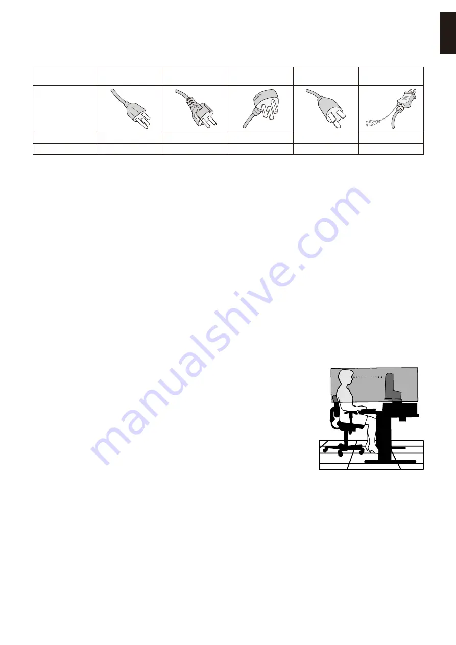
background image

English−9

English

Power Cord Table

Plug Type

North America

European 

Continental

U.K.

Chinese

Japanese

Plug Shape

Region

U.S.A./Canada

EU

U.K.

China

Japan

Voltage

120*

230

230

220

100

*  Please use this power cord under 125 V power supply. 

OOTEN:  

This product can only be serviced in the country where it was purchased.

Image Persistence
Image Persistence, also called Image Retention, is a condition that occurs when a previously displayed image leaves a 

residual or “ghost” impression on the screen. This happens when a single still image is shown for an extended time or when 

an image tremors or flashes at high speed. This is due to the technology of the LCD module and screen characteristics; it is 

not a product failure. While a residual image may disappear over time depending on the product usage, there is no guarantee 

Image Persistence will resolve itself. Please follow these guidelines to care for the product and reduce the chance of Image 

Persistence occurring:
OOTEN  •

Do not display images with repeated tremors or flashing at high speeds.

 •

Do not display a single still image for an extended period of time.

One of the methods to avoid Image Persistence is to frequently switch the displaying image using computer power management 

or screen savers.

Ergonomics

CORRECT PLACEMENT AND ADJUSTMENT OF THE MONITOR CAN 

REDUCE EYE, SHOULDER, AND NECK FATIGUE. CHECK THE 

FOLLOWING WHEN YOU POSITION THE MONITOR:

To realize the maximum ergonomics benefits, we recommend the following:
•  For optimum performance of the monitor, allow 20 minutes for warming up. Avoid 

reproduction of still patterns on the monitor for long periods of time to avoid image 

persistence (after image effects).

•  Adjust the monitor height so that the top of the screen is at or slightly below eye level. 

Your eyes should look slightly downward when viewing the middle of the screen.

•  Position your monitor no closer than 40 cm (15.75 inches) and no further away than 

70 cm (27.56 inches) from your eyes. The optimal distance is 50 cm (19.69 inches).

•  Rest your eyes periodically for 5 to 10 minutes for every 1 hour by focusing on an object 

at least 20 feet away.

•  Position the monitor at a 90° angle to windows and other light sources to minimize glare 

and reflections. Adjust the monitor tilt so that ceiling lights do not reflect on your screen.

•  If reflected light makes it hard for you to see your screen, use an anti-glare filter.
•  Adjust the monitor’s brightness and contrast controls to enhance readability.
•  Use a document holder placed close to the screen.
•  Position whatever you are looking at most of the time (the screen or reference material) directly in front of you to minimize 

turning your head while you are typing.

•  Blink often. Eye exercise helps to reduce eye strain. Please contact your ophthalmologist. Get regular eye checkups.
•  To avoid eye fatigue, adjust the brightness to a moderate setting. Place a sheet of white paper next to the LCD screen for 

luminance reference.

•  Do not position the Contrast control to its maximum setting.
•  Use the preset Size and Position controls with standard signals.

Summary of Contents for MultiSync E224F

Page 1: ...E224F MultiSync E244F MultiSync E274F MODEL E224F E224F BK E244F E244F BK E274F E274F BK The regulations for this monitor applied to one of model names listed above Please find your model name on the...

Page 2: ...d for Mounting 20 Mount the Flexible Arm 20 Re attaching the Original Stand 21 Chapter 2 Basic Operation Using the OSD On Screen Display Controls 23 Changing the Input 24 Power management function LED...

Page 3: ...ere is no guarantee that interference will not occur in a particular installation If this equipment does cause harmful interference to radio or television reception which can be determined by turning...

Page 4: ...TION Please refer to CAUTION 2 The intended primary use of this product is as an Information Technical Equipment in an office or domestic environment The product is intended to be connected to a compu...

Page 5: ...cates a mandatory action This symbol indicates that the power cord should be unplugged from the power outlet WARNING 1 UNPLUG THE POWER CORD Unplug the power cord if the product malfunctions Should th...

Page 6: ...orresponds to the AC voltage of the power outlet and has been approved by and complies with the safety standards in the country of purchase 7 REQUIRED PROHIBITED Please install the product in accordan...

Page 7: ...ct set ALWAYS use furnitures that can safely support the product ALWAYS ensure the product is not overhanging the edge of the supporting furniture ALWAYS educate children about the dangers of climbing...

Page 8: ...electric shock or start a fire 12 PROHIBITED Do not use flammable gas sprays to remove dust when cleaning the product Doing so could lead to a fire 13 PROHIBITED Usage of the product must not be accom...

Page 9: ...let directly and earthed properly Do not use a 2 pin plug converter adapter 2 REQUIRED Please confirm the distribution system in building installation shall provide the circuit breaker rated 120 240 V...

Page 10: ...r any other purpose To avoid the danger of suffocation do not place this bag over your head nose or mouth Do not place this bag over another person s head nose or mouth Keep this bag away from childre...

Page 11: ...gonomics benefits we recommend the following For optimum performance of the monitor allow 20 minutes for warming up Avoid reproduction of still patterns on the monitor for long periods of time to avoi...

Page 12: ...ive cloth Avoid using any cleaning solution or glass cleaner Please do not rub the LCD Screen with hard or coarse material Please do not apply pressure to the LCD Screen surface Please do not use OA c...

Page 13: ...ly optimizing display performance Intelligent Power Manager System Provides innovative power saving methods that allow the monitor to shift to a lower power consumption level when on but not in use sa...

Page 14: ...English 12 Chapter 1 Installation and Connections This Chapter Includes Parts Name and Functions on page 13 Installation on page 15 Connections on page 16 Flexible Arm Installation on page 20...

Page 15: ...s key for 3 seconds or more LEFT RIGHT Opens the OSD menu RIGHT Enters sub menus or adjustment settings in the OSD menu when the OSD menu is open LEFT Exits the OSD sub menus adjustment settings and m...

Page 16: ...he audio out signal is always routed to the headphone jack when headphones are connected to the monitor there is no sound from the monitor speakers 7 Security Slot Security and theft protection lock s...

Page 17: ...the stand then tighten the screw at the base s bottom Figure 2 NOTE Reverse this procedure if you need to re pack the monitor WARNING Please refer to WARNING 8 Connect the power cord and signal cable...

Page 18: ...a maximum tilt angle and lift up to the highest position Figure 3 CAUTION Please refer to CAUTION 5 Maximum Tilt Up 25 Down 5 Figure 3 2 Connect devices to the monitor Turn off the power to your comp...

Page 19: ...n the center position may increase the ear headphones output voltage and therefore the sound pressure level Incorrect cable connections may result in irregular operation damage display quality compone...

Page 20: ...refer to the Caution section of this manual for proper selection of the AC power cord see page 9 Please make sure that enough power is supplied to the monitor Please refer to Power Supply in the Chap...

Page 21: ...mended 60 Hz Interlace signal is not supported NOTE When the selected monitor resolution is not a native panel resolution the text contents appearance in the monitor screen is expanded in a horizontal...

Page 22: ...monitor stand before mounting WARNING Please refer to WARNING 8 See the Specifications on page 28 for details Remove the Monitor Stand for Mounting NOTE Handle with care when removing the monitor sta...

Page 23: ...aching the Original Stand Reverse the process in the previous section to re attach stand NOTE Match TOP SIDE mark on stand to top side of the monitor when re attaching stand TOP SIDE mark Please match...

Page 24: ...English 22 Chapter 2 Basic Operation This Chapter Includes Using the OSD On Screen Display Controls on page 23 Changing the Input on page 24 Power management function LED indicator patterns on page 24...

Page 25: ...e adjustments or selections 1 UP key 2 DOWN key 3 RIGHT key 4 LEFT key Adjustment Settings Sub menu Main Menu Selected Main Menu name Below is a brief summary of where controls are under each menu ite...

Page 26: ...ly produced Blu rays and DVDs television broadcast and streaming media services Power management function LED indicator patterns The power management function is an energy saving feature that automati...

Page 27: ...English 25 English Chapter 3 Troubleshooting This Chapter Includes Screen Image and Video Signal Issues on page 26 Hardware Issues on page 27...

Page 28: ...ected device outputs a signal to the monitor Image Persistence If a ghost or residual image occurs please check Image Persistence see page 9 The image is unstable unfocused or swimming is apparent Mak...

Page 29: ...cted mouse When using DisplayPort some display cards do not output video signal under low resolution modes when the monitor is turned OFF ON or disconnected connected from the AC power cord No Sound C...

Page 30: ...English 28 Chapter 4 Specifications This Chapter Includes E224F on page 29 E244F on page 30 E274F on page 31...

Page 31: ...2 inches 260 3 mm 10 2 inches 478 7 mm 18 8 inches AUDIO AUDIO Input STEREO Mini Jack DisplayPort Connector HDMI Connector Analog Audio Digital Audio Digital Audio Stereo L R 500mV rms 20 Kohm PCM 2c...

Page 32: ...6 5 mm 11 7 inches 527 0 mm 20 7 inches AUDIO AUDIO Input STEREO Mini Jack DisplayPort Connector HDMI Connector Analog Audio Digital Audio Digital Audio Stereo L R 500mV rms 20 Kohm PCM 2ch 32 44 1 48...

Page 33: ...336 3 mm 13 2 inches 597 9 mm 23 5 inches AUDIO AUDIO Input STEREO Mini Jack DisplayPort Connector HDMI Connector Analog Audio Digital Audio Digital Audio Stereo L R 500mV rms 20 Kohm PCM 2ch 32 44 1...

Page 34: ...ntrols List This Chapter Includes Luminance on page 33 Image Setup on page 33 Color Setup on page 33 OSD Setup on page 34 System Setup on page 34 Extra on page 34 OSD Warning on page 34 Default values...

Page 35: ...ht of the screen Narrows the width of the image on the left of the screen Fine Analog input only Adjusts the visual noise in the image Expansion Sets the Zoom method Full The image is expanded to full...

Page 36: ...he volume of the speakers or headphones DDC CI Turns the DDC CI function On or Off OSD Warning NO SIGNAL This function gives a warning when there is no horizontal or vertical sync After power is turne...

Page 37: ...page 36 We are strongly committed to environmental protection and sees recycling as one of the company s top priorities in trying to minimize the burden placed on the environment We are engaged in de...

Page 38: ...mode is activated The monitor enters a single Energy Saving mode For additional information visit https www sharpnecdisplays us in USA https www sharpnecdisplays eu p hq en home xhtml in Europe https...

Reviews: